HAL740 Ver la hoja de datos (PDF) - Micronas
Número de pieza
componentes Descripción
Fabricante
HAL740 Datasheet PDF : 22 Pages
| |||
HAL700, HAL740
DATA SHEET
5. Application Notes
5.1. Ambient Temperature
Due to the internal power dissipation, the temperature
on the silicon chip (junction temperature TJ) is higher
than the temperature outside the package (ambient
temperature TA).
TJ = TA + ΔT
At static conditions and continuous operation, the fol-
lowing equation applies:
ΔT = IDD * VDD * Rth
For typical values, use the typical parameters. For
worst case calculation, use the max. parameters for
IDD and Rth, and the max. value for VDD from the appli-
cation.
For all sensors, the junction temperature range TJ is
specified. The maximum ambient temperature TAmax
can be calculated as:
TAmax = TJmax − ΔT
5.2. Extended Operating Conditions
All sensors fulfill the electrical and magnetic character-
istics when operated within the Recommended Oper-
ating Conditions (see Section 3.5. on page 11).
Supply Voltage Below 3.8 V
Typically, the sensors operate with supply voltages
above 3 V, however, below 3.8 V some characteristics
may be outside the specification.
Note: The functionality of the sensor below 3.8 V is not
tested. For special test conditions, please con-
tact Micronas.
5.3. Start-up Behavior
Due to the active offset compensation, the sensors
have an initialization time (enable time ten(O)) after
applying the supply voltage. The parameter ten(O) is
specified in the “Characteristics” (see Section 3.6. on
page 12).
During the initialization time, the output states are not
defined and the outputs can toggle. After ten(O), both
outputs will be either high or low for a stable magnetic
field (no toggling). The outputs will be low if the applied
magnetic flux density B exceeds BON and high if B
drops below BOFF.
For magnetic fields between BOFF and BON, the output
states of the Hall sensor after applying VDD will be
either low or high. In order to achieve a well-defined
output state, the applied magnetic flux density must be
above BONmax, respectively, below BOFFmin.
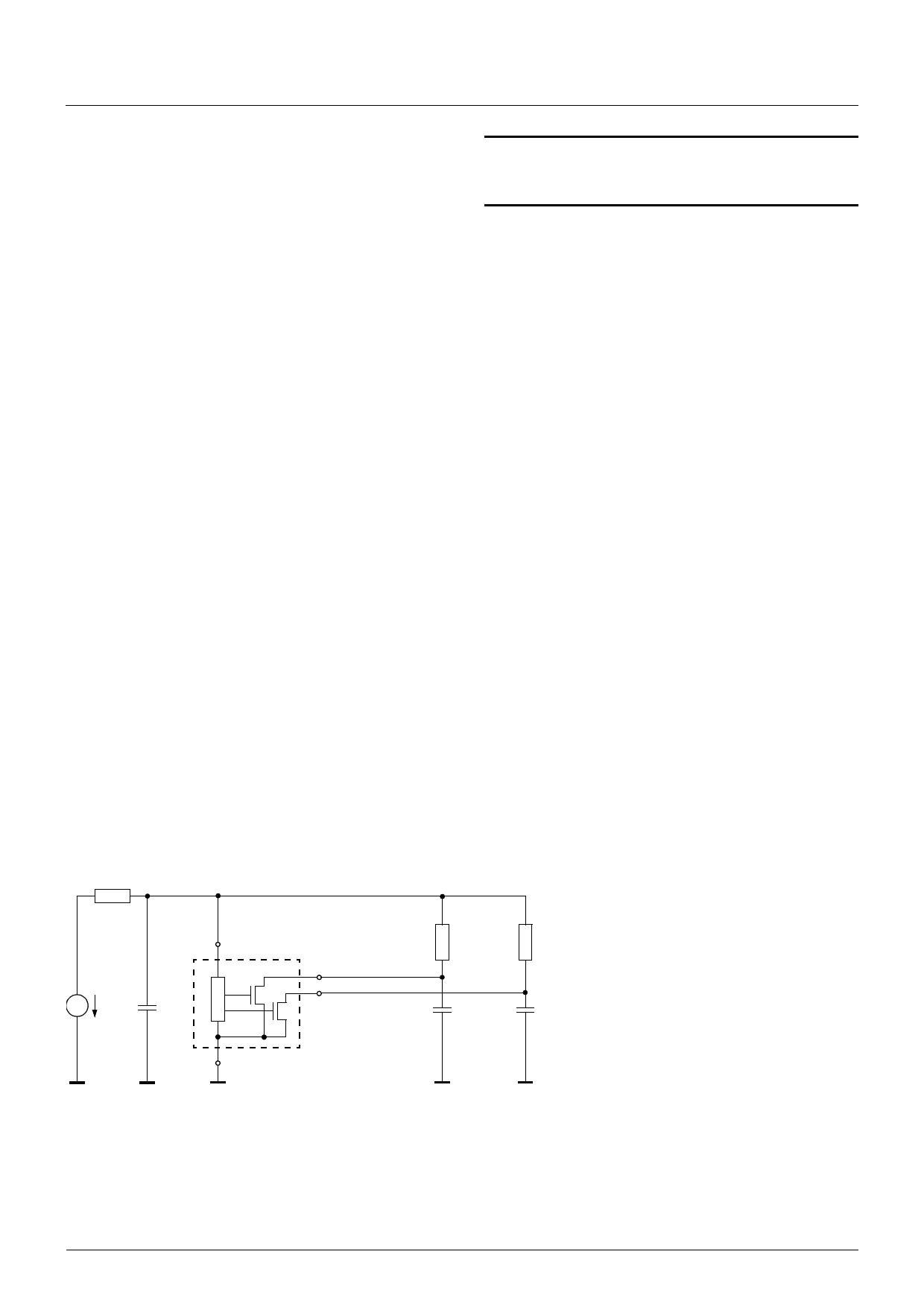
5.4. EMC and ESD
For applications that cause disturbances on the supply
line or radiated disturbances, a series resistor and a
capacitor are recommended (see Fig. 5–1). The series
resistor and the capacitor should be placed as closely
as possible to the Hall sensor.
Please contact Micronas for detailed investigation
reports with EMC and ESD results.
RV
220 Ω
VEMC
VP
1 VDD
4.7 nF
3 S1-Output
2 S2-Output
RL 2.4 kΩ RL 2.4 kΩ
20 pF
20 pF
4 GND
Fig. 5–1: Test circuit for EMC investigations
20
Nov. 30, 2009; DSH000029_002EN
Micronas
Share Link: 