XE1203F Ver la hoja de datos (PDF) - Semtech Corporation
Número de pieza
componentes Descripción
Fabricante
XE1203F Datasheet PDF : 36 Pages
| |||
XE1203F
FSParam_Br
Bit rate (bit/s)
1111110
0111111
0011111
0001111
0000111
0000011
0000001
others (*)
1200
2400
4800
9600
19200
38400
76800
153000
Table 8: Possible bit rates and frequency deviations when pre-filtering is enabled
(*) For any programmed value of FSParam_Br which is not in the Table 8 above, the data-rate is fixed to 153 kbit/s
and the pre-filtering is applied as defined by the user.
If ADParam_enable_konex is set high, then the pre-filtering option is available for a bit rate of 32.7 kbit/s and one of
the frequency deviations defined above.
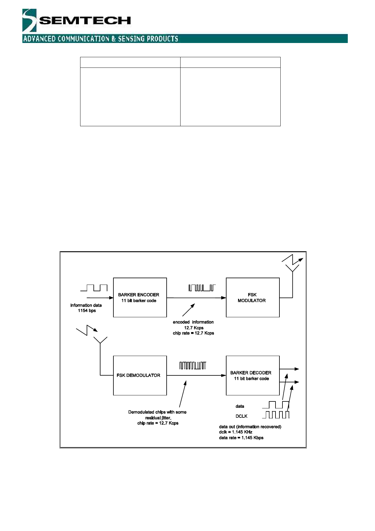
4.2.2 Barker encoder/decoder
The Barker encoder/decoder hardware can be activated to modulate/demodulate the transmitted signal to reduce
in-band interferences The Barker decoder provides an alternative to the bit synchronizer only for a fixed data rate
of 1154bits/s. The Barker block is selected when the RTParam_Barker configuration bit is set to “1”. In
transmission, the information data at a bit rate of 1154bits/s is spread using an 11-bit Barker code. The result is an
encoded bit stream at 12.7 kilochips per second (kcps), which is applied to the frequency synthesizer. On the
receiver part, the signal is demodulated using the FSK demodulator (at 12.7 kcps) and then fed into the Barker
decoder to recover the un-encoded data at 1154 bit/s, together with a synchronized clock to sample it. Figure 8 on
the next page, illustrates the coding/decoding process.
Figure 9: Barker Encoding and Decoding Channels.
In receiver mode, the XE1203F provides a clock output, DCLK, to a microcontroller. The data can be sampled at
the rising edge of the clock. When using the Barker decoding process, DCLK is used to detect the sync acquisition.
If there is no valid data, DCLK remains high. The first falling edge of the clock means that the sync acquisition
phase has been reached and that the output data is now available. This is illustrated below in Figure 10.
© Semtech 2007
www.semtech.com
15
Share Link: 