CMX615D4 Ver la hoja de datos (PDF) - MX-COM Inc
Número de pieza
componentes Descripción
Fabricante
CMX615D4 Datasheet PDF : 26 Pages
| |||
Digital Line to POTS Interface
CMX615
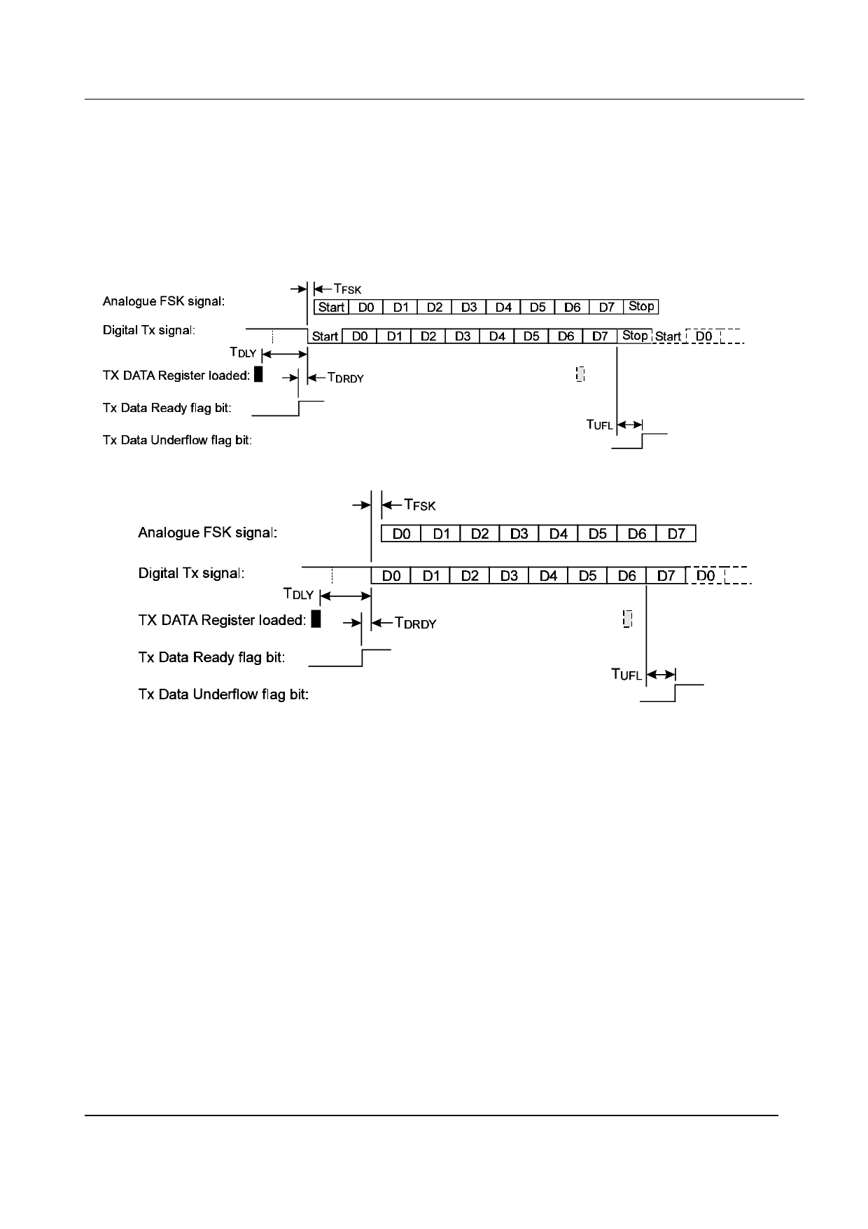
One Start bit (Space)
Eight Data bits (D0-D7) from the TX DATA Register, with the lsb (D0) transmitted first
One Stop bit (Mark)
Failure to load the TX DATA Register with a new value when required will result in bit 7 (Tx Data Underflow) of
the STATUS Register being set to ‘1’. If the ‘Tx Async’ mode of operation is selected then a continuous Mark
(‘1’) signal will be transmitted until a new value is loaded into TX DATA. If the ‘Tx Sync’ mode is selected then
the byte already in the TX DATA Register will be re-transmitted.
Figure 3a Async mode
Figure 3b Sync mode
1.5.7 ‘C-BUS’ Interface
This block provides for the transfer of data and control or status information between the CMX615’s internal
registers and the µC over the ‘C-BUS’ serial bus. Each transaction consists of a single Register Address byte
sent from the µC which may be followed by a single data byte sent from the µC to be written into one of the
CMX615’s Write Only Registers, or a single byte of data read out from one of the CMX615’s Read Only
Registers, as illustrated in Figure 4.
Data sent from the µC on the Command Data (COMDATA) line is clocked into the CMX615 on the rising edge
of the Serial Clock (SERCK) input. Reply Data (REPDATA) sent from the CMX615 to the µC is valid when the
Serial Clock is high. The interface is compatible with the most common µC serial interfaces such as SCI, SPI
and Microwire, and may also be easily implemented with general purpose µC I/O pins controlled by a simple
software routine. See Figure 8 for detailed ‘C-BUS’ timing requirements.
© 1999 Consumer Microcircuits Limited
11
D/615/4
Share Link: 