UPD160061AN Ver la hoja de datos (PDF) - NEC => Renesas Technology
Número de pieza
componentes Descripción
Fabricante
UPD160061AN
NEC => Renesas Technology

UPD160061AN Datasheet PDF : 18 Pages
| |||
µPD160061A
★ Electrical Characteristics (TA = –10 to +75°C, VDD1 = 2.3 to 3.6 V, VDD2 = 7.5 to 9.5 V, VSS1 = VSS2 = 0 V)
Parameter
Symbol
Condition
MIN.
TYP.
MAX. Unit
Input Leak Current
IIL
Except LPC, HPC, SRC
±1.0
µA
LPC, HPC, SRC
±150
µA
High-Level Output Voltage VOH
STHR (STHL), IOH = 0 mA
VDD1 – 0.1
V
Low-Level Output Voltage VOL
γ -Corrected Resistance
Rγ
Driver Output Current
IVOH
IVOL
STHR (STHL), IOL = 0 mA
V0 to V4 = V5 to V9 = 4.0 V, VDD2 = 8.5 V
7.9
VDD2 = 8.0 V, VX = 7.0 V, VOUT = 6.5 V Note1
VDD2 = 8.0 V, VX = 1.0 V, VOUT = 1.5 V Note1
20
0.1
V
15.8
23.7
kΩ
– 20
µA
µA
Output Voltage Deviation
Output Swing Difference
Deviation
∆VO
∆VP–P
TA = 25°C,
VDD1 = 3.3 V, VDD2 = 8.5 V,
VOUT = 2.0 V, 4.25 V, 6.5 V
±10
±20
mV
±3
±15
mV
Logic Part Dynamic Current IDD1
Consumption Note2, 3, 4
VDD1
4
12
mA
Driver Part Dynamic Current IDD22
Consumption Note2, 4
VDD2, with no load
3.5
8
mA
Notes1. VX refers to the output voltage of analog output pins S1 to S384. VOUT refers to the voltage applied to analog output
pins S1 to S384.
2. Specified at fSTB = 65 kHz and fCLK = 54 MHz.
3. The TYP. values refer to an all black or all white input pattern. The MAX. value refers to the measured values in
the dot checkerboard input pattern.
4. Refers to the current consumption per driver when cascades are connected under the assumption of XGA
single-sided mounting (8 units).
Switching Characteristics (TA = –10 to +75°C, VDD1 = 2.3 to 3.6 V, VDD2 = 7.5 to 9.5 V, VSS1 = VSS2 = 0 V)
Parameter
Symbol
Condition
MIN.
TYP.
MAX.
Unit
Start Pulse Delay Time
tPLH1
CL = 15 pF, 2.3 V ≤ VDD1 < 2.7 V
20
ns
CL = 10 pF, 2.7 V ≤ VDD1 ≤ 3.6 V
10.5
ns
tPLH1
CL = 10 pF, 2.3 V ≤ VDD1 < 2.7 V
20
ns
CL = 10 pF, 2.7 V ≤ VDD1 ≤ 3.6 V
10.5
ns
Driver Output Delay Time tPLH2
CL = 75 pF, RL = 5 kΩ,
5
µs
tPLH3
tPHL2
tPHL3
LPC = L or open,
HPC = H or open,
SRC = H or open
8
µs
5
µs
8
µs
Input Capacitance
CI1
Logic input of exclude STHR (STHL),
TA = 25°C
10
pF
CI2
STHR (STHL), TA = 25°C
5
pF
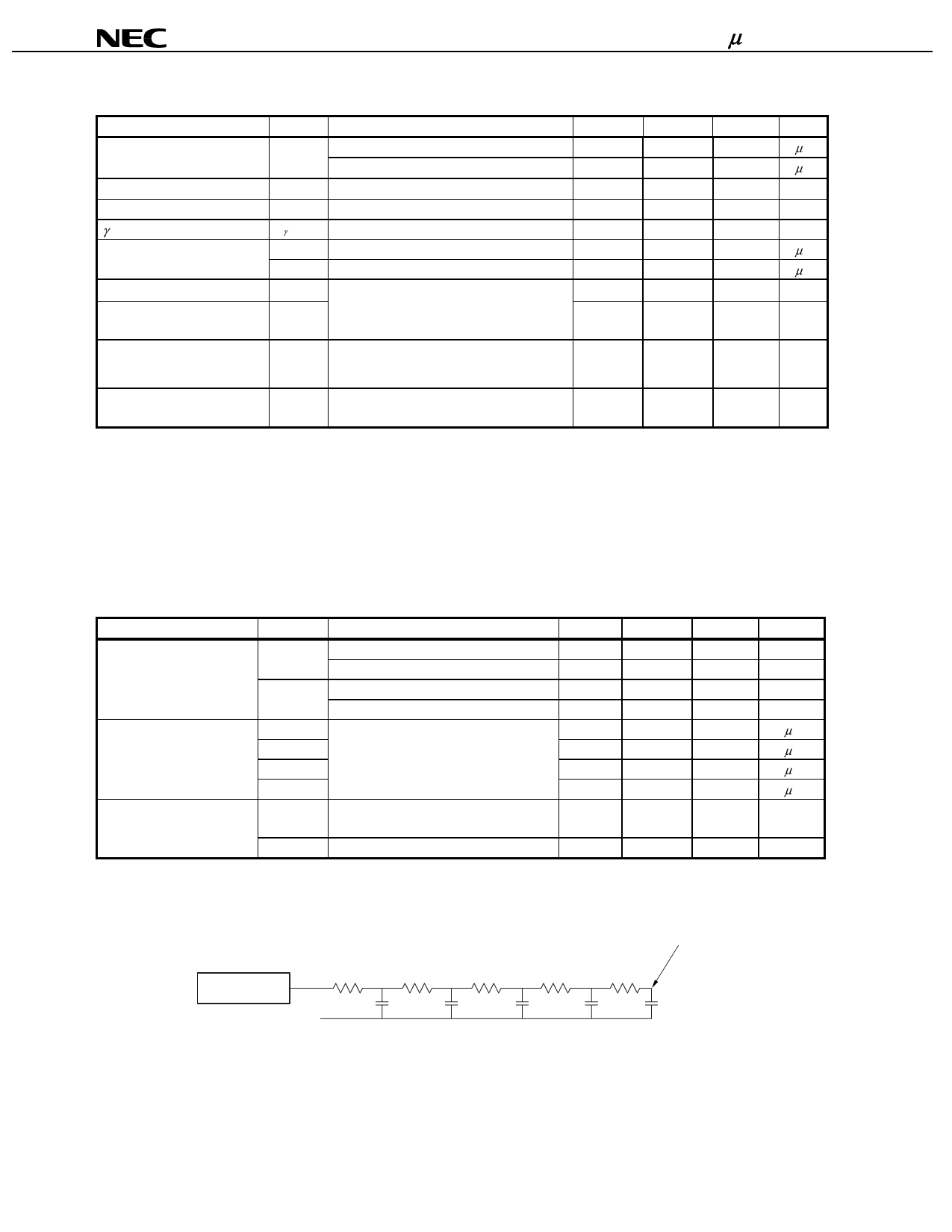
<Measurement condition>
RLn = 1 kΩ, CLn = 15 pF
RL1
Output
GND
RL2
CL1
RL3
CL2
RL4
CL3
The measurement point
RL5
CL4
CL5
14
Data Sheet S16041EJ2V0DS
Share Link: