TK65910 Ver la hoja de datos (PDF) - Toko America Inc
Número de pieza
componentes Descripción
Fabricante
TK65910 Datasheet PDF : 20 Pages
| |||
TK6591x
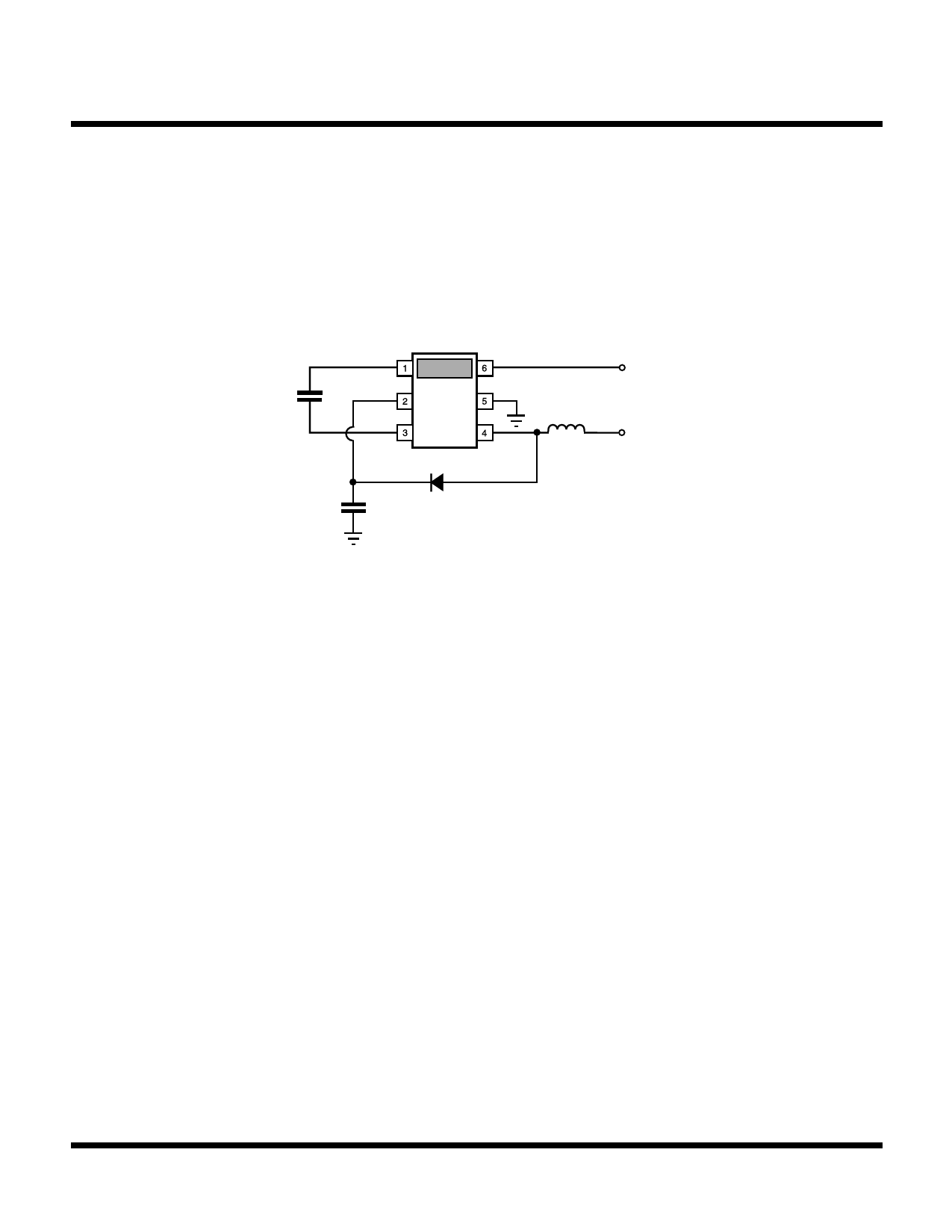
APPLICATION INFORMATION
LOW VOLTAGE SPLIT SUPPLY APPLICATION
The split power supply application of this EL driver IC is a circuit configuration (see Figure 4) in which the VCC IC power
(Vcontrol) is separated or split away from the main power input (Vpower) supplying current to the inductor.
CEL
5 nF
EL +
HV
EL -
VCC
GND
Vcontrol
from
2.7 to 6 V
max. 200 µA
IND
Vpower
L1
from
0.9 to 20 V
C1
D1
22 nF
FIGURE 4: SPLIT SUPPLY APPLICATION CIRCUIT
The voltage supplied to the VCC pin of the IC (Vcontrol) needs to be maintained in the 2.7 V to 6.0 V range, but the current
draw on this power supply rail of the system would be very small (under 200 µA). This Vcontrol can be used to turn on and
off the EL lamp driver, which permits the Vpower to be connected to the battery or other power source directly with the
least amount of resistance in the power path as possible.
Now with the VCC power for the IC (Vcontrol) being supplied from a different source, the main power (Vpower) can be any
voltage between 0.9 V and 20 V. But it is critical to properly select the inductor such that the proper peak current
regulation is maintained over the input voltage operating range of the converter.
If the inductor value is too large the current will rise too slowly and not have time to reach its set peak current trip point
at low input voltages, but at high input voltage the current might rise too quickly and overshoot the set peak current trip
point.
The primary low voltage battery applications for this part are in a single cell or a dual cell alkaline system (such as a pager
or PDA). These systems are assumed to have a minimum useable input voltage of 0.9 V for the single cell system and
1.8 V for the dual cell system.
For low converter input voltages (0.9 V and 1.8 V minimum input voltages), the following Table 5 shows the recommended
maximum inductance value for a given device part number (therefore a given frequency of operation) and a minimum
input voltage. Each cell in the table gives three inductance values; each value (in µH) corresponds to each type of
specialized Toko EL driver inductors (D31FU, D32FU, and D52FU types of Toko inductors).
Page 14
May 2000 TOKO, Inc.
Share Link: 