TK10931VTL Ver la hoja de datos (PDF) - Toko America Inc
Número de pieza
componentes Descripción
Fabricante
TK10931VTL Datasheet PDF : 26 Pages
| |||
TK10931V
CIRCUIT DESCRIPTION (CONT.)
(3) FM-IF Limiter Amplifier, RSSI
The IF limiter amplifier is composed of 6 differential gain
stages. The total gain of the IF limiter amplifier is 80 dB at
455 kHz. The output signal of the IF limiter amplifier is
provided at Pin 10 through the emitter-follower output
stage. The IF limiter amplifier output level is 0.5 VP-P. The
operating current of the emitter-follower at the IF limiter
amplifier is 200 µA.
If the capacitive load is heavy, the negative half cycle of the
output waveform may be distorted. This can be improved
by connecting an external resistor between Pin 10 and
GND to increase the operating current. The increased
operating current by an external resistor is calculated as
follows (see Figure 7):
The increased operating current Ie(mA) = (VCC - 1.0)/
Re(kΩ)
VCC
Current Output
RSSI OUT
I-V Converting Resistor
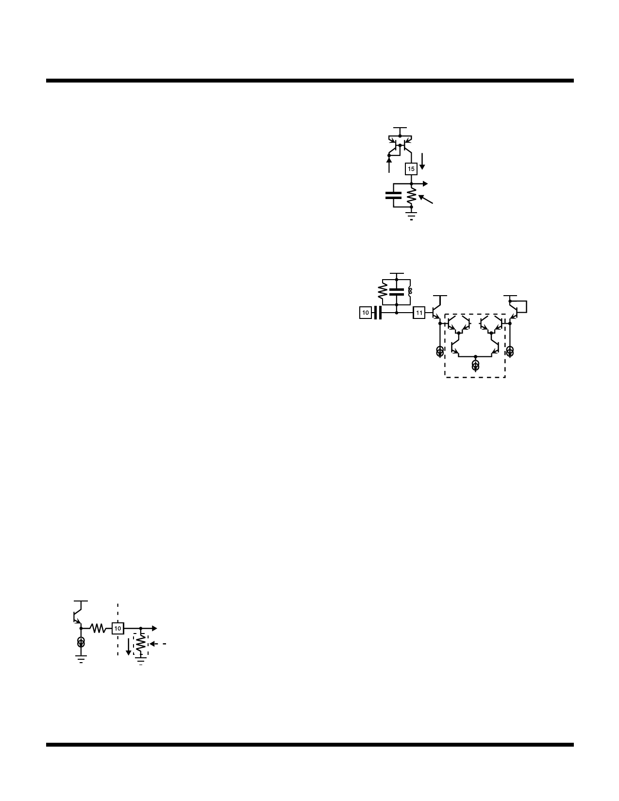
FIGURE 8: RSSI OUTPUT EQUIVALENT CIRCUIT
VCC
VCC
VCC
QB
The RSSI output is a current output. It is converted to a
voltage by an external resistor connected between Pin 15
and GND. The time constant of the RSSI output is
determined by the product of the external converting
resistance and the parallel capacitance. When the time
constant is longer, the RSSI output response is slower.
Determine the external resistance and capacitance by the
application. The slope of the RSSI curve characteristics
can be changed by changing the external resistance. In
this case, the maximum range of converted RSSI output
voltage is from GND level to about VCC-0.2 V (the supply
voltage minus the collector saturation voltage of the output
transistor). In addition, the temperature characteristic of
the RSSI output voltage can be changed by changing the
temperature characteristic of the external resistor.
Normally, the temperature characteristic of the RSSI
output voltage is very stable when using a carbon resistor
or metal film resistor with a temperature characteristic of 0
to 200 ppm/°C.
VCC
100
200 µA
IF OUT
Re
Ie
The emitter-follower operating
current can be increased by
external resistor Re when the
capacitive load is heavy and
the waveform distortion will be
reduced.
FIGURE 7
FIGURE 9: FM DETECTOR EQUIVALENT CIRCUIT
(4) FM Detector
The FM detector is included in the Quadrature FM detector
using a Gilbert multiplier. The phase shifter is connected
between Pin 10 (IF limiter output) and Pin 11 (detector
input), with any available phase shifter. A phase shifter can
be used such as the LC resonance circuit, the ceramic
discriminator, and the delay line. Figure 11 shows the
internal equivalent circuit of the detector. The signal from
the phase shifter is applied to the multiplier (in the dotted
line) through emitter-follower stage QA. Note that Pin 11
must have the bias voltage impressed from an external
source, because Pin 11 is connected with the base of QA
only. Because the base of QB of the opposite side is
connected with the supply voltage, Pin 11 has to be biased
with the equivalent voltage. Using an LC resonance circuit
is not a problem (see Figure 10), but attention must be paid
when using a ceramic discriminator. If the base voltages
are different, the DC voltage of the multiplier does not
balance. This alters the DC zero point or worsens the
distortion of the demodulation output. The Pin 11 input
level should be saturated at the multiplier, if this level is
lower, it is easy to disperse the detector output. Therefore,
to be in stable operation, the Pin 16 input level should be
higher than 100 mVP-P. Figure 10 shows examples of
phase shifters.
Page 20
January 2001 TOKO, Inc.
Share Link: 