TC1017 Ver la hoja de datos (PDF) - Microchip Technology
Número de pieza
componentes Descripción
Fabricante
TC1017 Datasheet PDF : 22 Pages
| |||
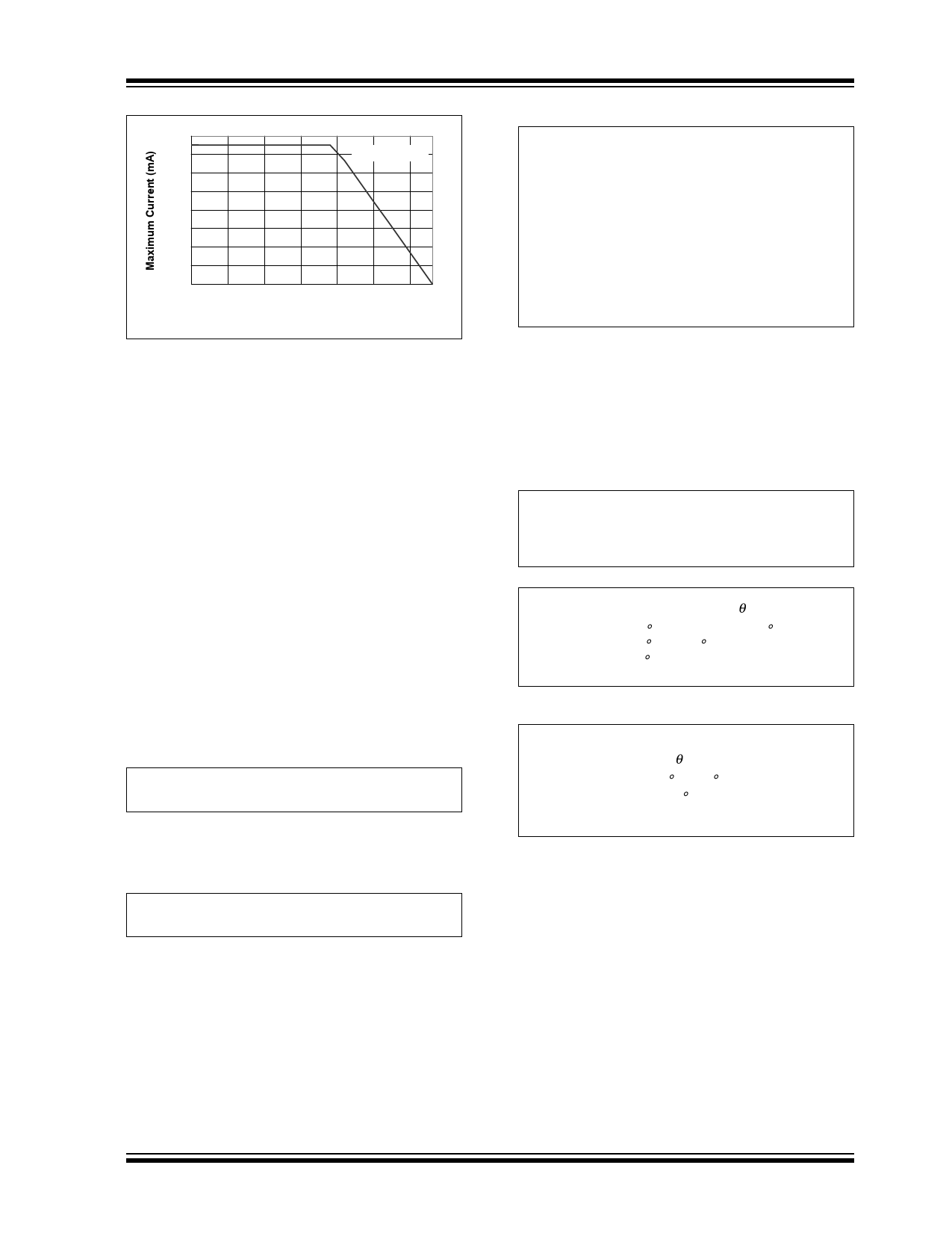
160
140
120
100
80
60
40
20
0
-40
VIN - VOUT = 1V
-15 10 35 60 85 110
Ambient Temperature (°C)
FIGURE 5-2:
Maximum Current vs.
Ambient Temperature (SC-70 package).
5.3 Power Dissipation: SOT-23
The TC1017 is also available in a SOT-23 package for
improved thermal performance. The thermal resistance
for the SOT-23 package is approximately 255°C/W
when the copper area used in the printed circuit board
layout is similar to the JEDEC J51-7 low thermal
conductivity standard or semi-G42-88 standard. For
applications with larger or thicker copper area, the
thermal resistance can be lowered. See AN792, “A
Method to Determine How Much Power a SOT-23 Can
Dissipate in an Application”, DS00792, for a method to
determine the thermal resistance for a particular
application.
The TC1017 power dissipation capability is dependant
upon several variables: input voltage, output voltage,
load current, ambient temperature and maximum
junction temperature. The absolute maximum steady-
state junction temperature is rated at +125°C. The
power dissipation within the device is equal to:
EQUATION:
PD = (VIN – VOUT) × ILOAD + VIN × IGND
The VIN x IGND term is typically very small when
compared to the (VIN-VOUT) x ILOAD term, simplifying the
power dissipation within the LDO to be:
EQUATION:
PD = (VIN – VOUT) × ILOAD
To determine the maximum power dissipation
capability, the following equation is used:
TC1017
EQUATION:
PDMAX
=
(---T---J--_--M-----A---X-----–-----T---A---_---M----A---X----)-
RθJA
Where:
TJ_MAX = the maximum junction
temperature allowed
TA_MAX = the maximum ambient
temperature
RθJA = the thermal resistance from
junction to air
Given the following example:
Find:
VIN =
VOUT =
ILOAD =
TA =
3.0V to 4.1V
2.85V ±2.5%
120 mA (output current)
+85°C (max. desired ambient)
1. Internal power dissipation:
PDMA X = (VIN_MAX – VOUT_MIN ) × ILOAD
= (4.1V – 2.85 × (0.975)) × 120mA
= 158.5mW
2. Maximum allowable ambient temperature:
TA_MAX = TJ_MAX – PDMAX × RθJA
= (125°C – 158.5mW × 255°C/W)
= (125°C – 40.5°C)
= 84.5°C
3. Maximum allowable power dissipation at
desired ambient:
PD
=
T----J--_---M----A--X-----–----T----A-
RθJA
= -1--2----5---°--C------–-----8---5---°---C--
255°C/W
= 157mW
In this example, the TC1017 dissipates approximately
158.5 mWatts and the junction temperature is raised
40.5°C over the ambient. The absolute maximum
power dissipation is 157 mW when given a maximum
ambient temperature of +85°C.
Input voltage, output voltage or load current limits can
also be determined by substituting known values in the
power dissipation equations.
Figure 5-3 and Figure 5-4 depict typical maximum
power dissipation versus ambient temperature and
typical maximum current versus ambient temperature
with a one volt input voltage to output voltage
differential, respectively.
2003 Microchip Technology Inc.
DS21813B-page 13
Share Link: 