NCV8667 Ver la hoja de datos (PDF) - ON Semiconductor
Número de pieza
componentes Descripción
Fabricante
NCV8667 Datasheet PDF : 20 Pages
| |||
NCV8667
1
Vin
SI
EN
DT
SO−8
8
Vout
SO
RO
GND
1
EN
DT
GND
GND
GND
GND
RO
14
SI
Vin
GND
GND
GND
Vout
SO
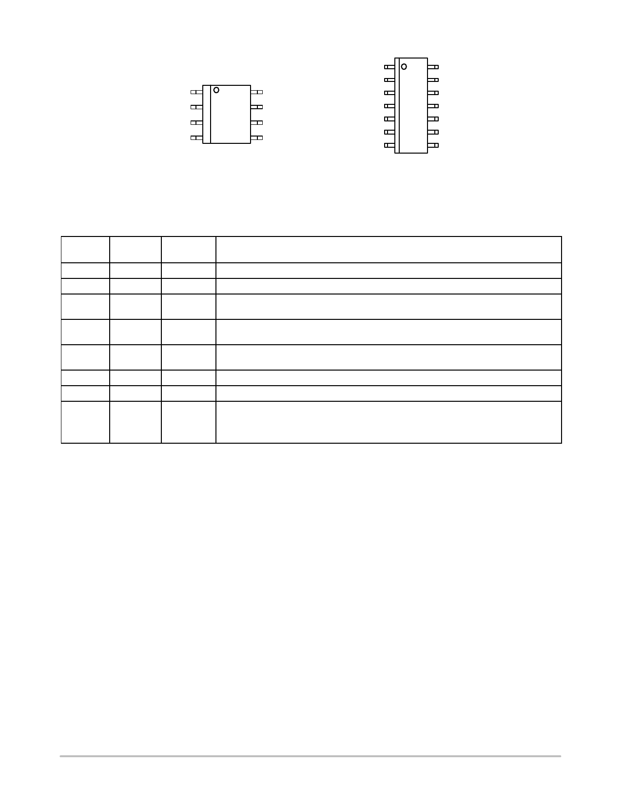
Figure 5. Pin Connections
(Top View)
SO−14
PIN FUNCTION DESCRIPTION
Pin No.
SO−8
Pin No.
SO−14
Pin Name
3
1
EN
4
2
DT
5
3, 4, 5, 6,
GND
10, 11, 12
6
7
RO
7
8
SO
8
9
Vout
1
13
Vin
2
14
SI
Description
Enable Input; low level disables the IC.
Reset Delay Time Select. Short to GND or connect to Vout to select time.
Power Supply Ground.
Reset Output. 30 kW internal Pull−Up resistor connected to Vout. RO goes Low when Vout
drops by more than 7% (typ.) from its nominal value
Early Warning Output. 30 kW internal Pull−Up resistor connected to Vout. It can be used to
provide early warning of an impending reset condition. Leave open if not used.
Regulated Output Voltage. Connect 2.2 mF capacitor with ESR < 100 W to ground.
Positive Power Supply Input. Connect 0.1 mF capacitor to ground.
Adjustable Early Warning Threshold: Sense Input; If not used, connect to Vout.
Preset Early Warning Threshold: Early Warning Adjust Input; connect RSI_ext against GND
to adjust Input Voltage Early Warning Threshold or leave unconnected. See Electrical
Characteristics Table and Application Information sections for more information.
http://onsemi.com
4
Share Link: 