MPC7448 Ver la hoja de datos (PDF) - Freescale Semiconductor
Número de pieza
componentes Descripción
Fabricante
MPC7448 Datasheet PDF : 60 Pages
| |||
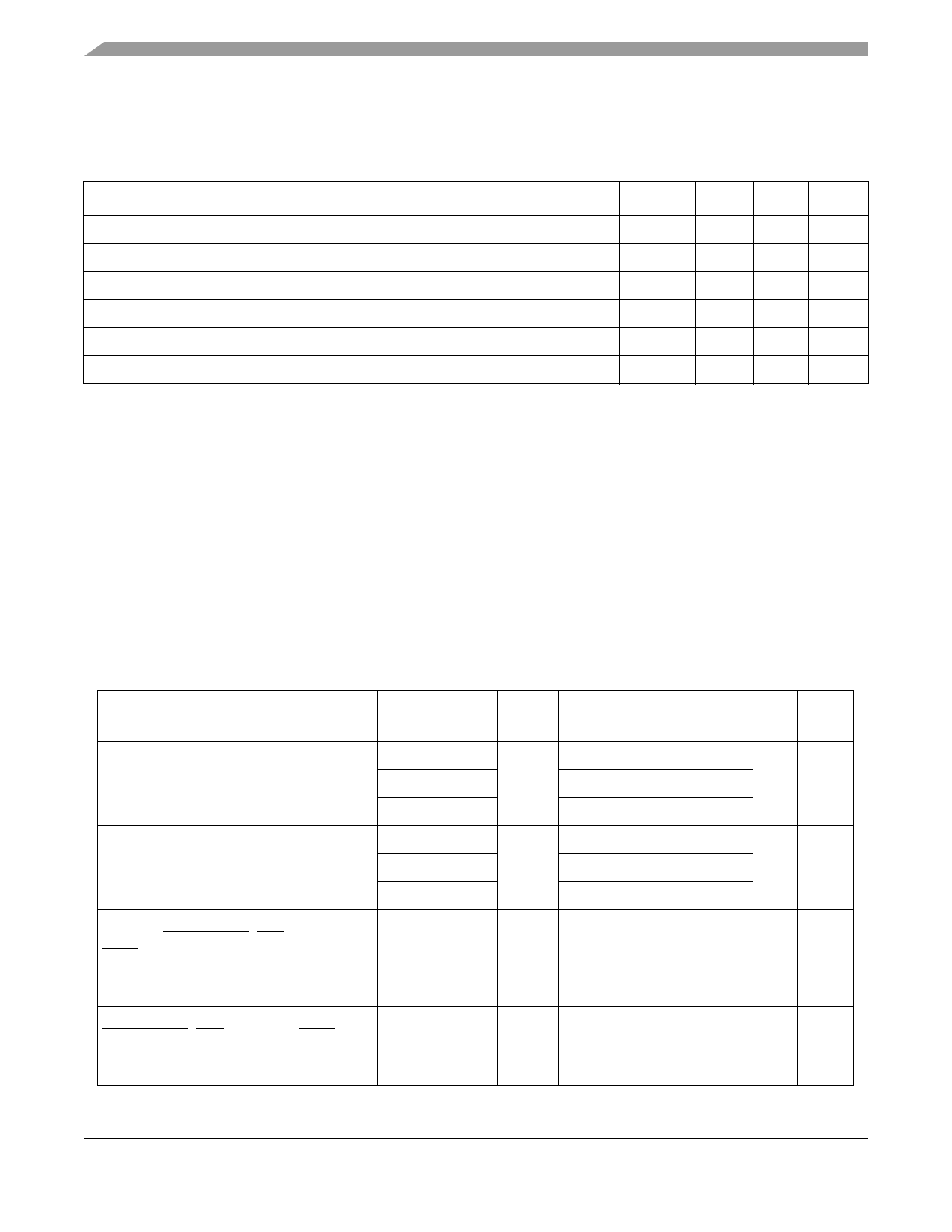
Electrical and Thermal Characteristics
Table 5 provides the package thermal characteristics for the MPC7448. For more information regarding
thermal management, see Section 9.7, “Power and Thermal Management Information.”
Table 5. Package Thermal Characteristics1
Characteristic
Symbol Value Unit Notes
Junction-to-ambient thermal resistance, natural convection, single-layer (1s) board
RθJA
26 •C/W 2, 3
Junction-to-ambient thermal resistance, natural convection, four-layer (2s2p) board
RθJMA
19 •C/W 2, 4
Junction-to-ambient thermal resistance, 200 ft/min airflow, single-layer (1s) board
RθJMA
22 •C/W 2, 4
Junction-to-ambient thermal resistance, 200 ft/min airflow, four-layer (2s2p) board
RθJMA
16 •C/W 2, 4
Junction-to-board thermal resistance
RθJB
11 •C/W
5
Junction-to-case thermal resistance
RθJC
< 0.1 •C/W
6
Notes:
1. Refer to Section 9.7, “Power and Thermal Management Information,” for details about thermal management.
2. Junction temperature is a function of on-chip power dissipation, package thermal resistance, mounting site (board)
temperature, ambient temperature, airflow, power dissipation of other components on the board, and board thermal
resistance.
3. Per JEDEC JESD51-2 with the single-layer board horizontal
4. Per JEDEC JESD51-6 with the board horizontal
5. Thermal resistance between the die and the printed-circuit board per JEDEC JESD51-8. Board temperature is measured on
the top surface of the board near the package.
6. This is the thermal resistance between die and case top surface as measured by the cold plate method (MIL SPEC-883
Method 1012.1) with the calculated case temperature. The actual value of RθJC for the part is less than 0.1°C/W.
Table 6 provides the DC electrical characteristics for the MPC7448.
Table 6. DC Electrical Specifications
At recommended operating conditions. See Table 4.
Characteristic
Input high voltage
(all inputs)
Input low voltage
(all inputs)
Input leakage current, all signals except
BVSEL0, LSSD_MODE, TCK, TDI, TMS,
TRST:
Vin = OVDD
Vin = GND
Input leakage current, BVSEL0,
LSSD_MODE, TCK, TDI, TMS, TRST:
Vin = OVDD
Vin = GND
Nominal Bus
Voltage 1
Symbol
Min
Max
Unit Notes
1.5
VIH OVDD × 0.65 OVDD + 0.3 V
2
1.8
OVDD × 0.65 OVDD + 0.3
2.5
1.7
OVDD + 0.3
1.5
VIL
–0.3
OVDD × 0.35 V
2
1.8
–0.3
OVDD × 0.35
2.5
–0.3
0.7
—
Iin
—
µA 2, 3
50
– 50
—
Iin
—
µA 2, 6
50
– 2000
MPC7448 RISC Microprocessor Hardware Specifications, Rev. 4
12
Freescale Semiconductor
Share Link: 