TDA8779 Ver la hoja de datos (PDF) - Philips Electronics
Número de pieza
componentes Descripción
Fabricante
TDA8779 Datasheet PDF : 20 Pages
| |||
Philips Semiconductors
10-bit converter interface (ADC/DAC) for
quadrature transceiver
Objective specification
TDA8779
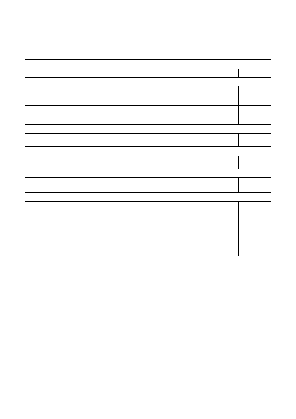
SYMBOL
PARAMETER
CONDITIONS
MIN. TYP. MAX. UNIT
Matching between channel I and Q
∆V
amplitude matching
∆ϕ
phase matching
DYNAMIC RANGE; note 2
NF
noise floor
SPURIOUS FREE DYNAMIC RANGE
SFDR
spurious free dynamic range
STANDBY MODE OUTPUT DELAY; STDBYD
fo = 5.1 MHz;
fCLK = 20 MHz;
Tamb = 25°C
fo = 5.1 MHz;
fCLK = 20 MHz;
Tamb = 25°C
fo = 5.1 MHz;
fCLK = 20 MHz
fo = 5.1 MHz;
fCLK = 20 MHz
−
−
6
%
−
−
2
Deg
−
−60 −
dB
−
50 −
dB
td(stb)LH
td(stb)HL
standby (LOW-to-HIGH transition)
start-up (HIGH-to-LOW transition)
CROSSTALK ON THE DAC
−
−
100 µs
−
−
100 µs
αct
crosstalk into the DAC
fCLK(DAC) = 16.384 MHz;
−
fCLK(ADC) = 8.192 MHz;
Tamb = 25°C; one DAC
switching between input
codes 0 and 1023 the other
DAC set at the middle
code; both ADCs 1 V (p-p)
sine wave at 4 MHz;
incoherent
−
−55 dB
Notes
1. It is recommended that the DAC output voltage is AC coupled in order to achieve optimum performance.
2. The noise floor is the maximum value of the output spectrum without taking into account fundamental and harmonics
of the input signal.
3. Harmonics are obtained via a Fast Fourier Transformer (FFT) treatment taking 8K acquisition points per period.
1996 Sep 18
10
Share Link: 