MC13158 Ver la hoja de datos (PDF) - Motorola => Freescale
Número de pieza
componentes Descripción
Fabricante
MC13158 Datasheet PDF : 24 Pages
| |||
MC13158
SYSTEM PERFORMANCE DATA
RSSI
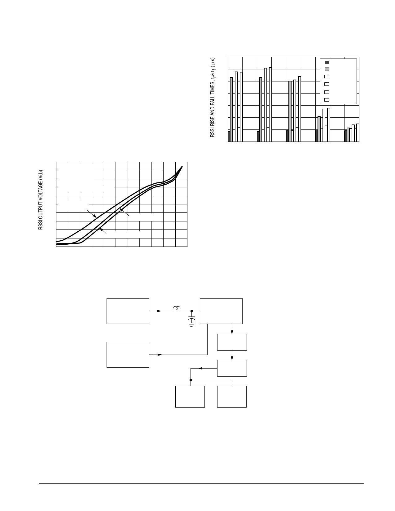
In Figure 22, the RSSI versus RF Input Level shows the
linear response of RSSI over a 65 dB range but it has
extended capability over 80 dB from – 80 dBm to +10 dBm.
The RSSI is measured in the application circuit (Figure 12) in
which a SAW filter is used before the mixer; thus, the overall
sensitivity is compromised for the sake of selectivity. The
curves are shown for three filters having different
bandwidths:
1) LCR Filter with 2.3 MHz 3.0 dB BW (Circuit and
Component Placement is shown in Figure 12)
2) Series–Parallel Ceramic Filter with 650 kHz 3.0 dB BW
(Murata Part # KMFC–545)
3) Ceramic Filter with 280 kHz 3.0 dB BW.
Figure 22. RSSI Output Voltage versus
Signal Input Level
3.0
2.7
VCC = 4.0 Vdc
fRF = 112 MHz
2.4 fLO = 122.7 MHz
2.1
fIF = 10.7 MHz
See Figure 12 for LCR filter
1.8
1.5 Series–Parallel
Ceramic Filter
1.2
0.9
Ceramic Filter
0.6
LCR; Rext = 150 Ω
0.3
0
– 90 – 80 –70 – 60 – 50 – 40 – 30 – 20 –10 0 10 20
SIGNAL INPUT LEVEL (dBm)
Figure 23. RSSI Output Rise and Fall Times
versus RF Input Signal Level
35
Ç 30
Ç Ç Ç 25
Ç Ç Ç 20
Ç Ç Ç ÉÇÉÇ 15
ÇÇ ÇÇ ÇÇ ÇÇÇ 10
ÉÇÉ ÉÇÉ ÉÇÉ ÉÇÉ ÉÇÇ 5.0
ÉÇÉ ÉÇÉ ÉÇÉ ÉÇÉ ÉÇÇ 0
ÉÇÉ ÉÇÉ ÉÇÉ ÉÇÉ ÉÇÇ 0
tr @
tf @
tr @
tf @
tr @
tf @
22 k
22 k
47 k
47 k
100
100
– 20
– 40
– 60
– 80
RF INPUT SIGNAL LEVEL (dBm)
SINAD Performance
Figure 24 shows a test setup for a narrowband
demodulator output response in which a C–message filter
and an active de–emphasis filter is used following the
demodulator. The input is matched using a 1:4 impedance
transformer. The SINAD performance is shown in Figure 25
with no preamp and in Figure 26 with a preamp (Preamp –
Figure 16). The 12 dB SINAD sensitivity is –101 dBm with no
preamp and –113 dBm with the preamp.
Figure 24. Test Setup for Narrowband SINAD
HP8657B
fc = 112 MHz
fmod = 1.0 kHz
∆f = ±125 kHz
Input
Match
HP8657B
fc = 122.7 MHz
PLO = – 6.0 dBm
LO
Output
MC13158
IF 3.0 dB BW = 280 kHz
LO
Detector Out
In
C–Message
Filter
Active
De–emphasis
HP334
Distortion
Analyzer
N+D
RF
Voltmeter
N
MOTOROLA ANALOG IC DEVICE DATA
19
Share Link: 