MBR16100 Ver la hoja de datos (PDF) - Kersemi Electronic Co., Ltd.
Número de pieza
componentes Descripción
Fabricante
MBR16100 Datasheet PDF : 2 Pages
| |||
CREAT BY ART
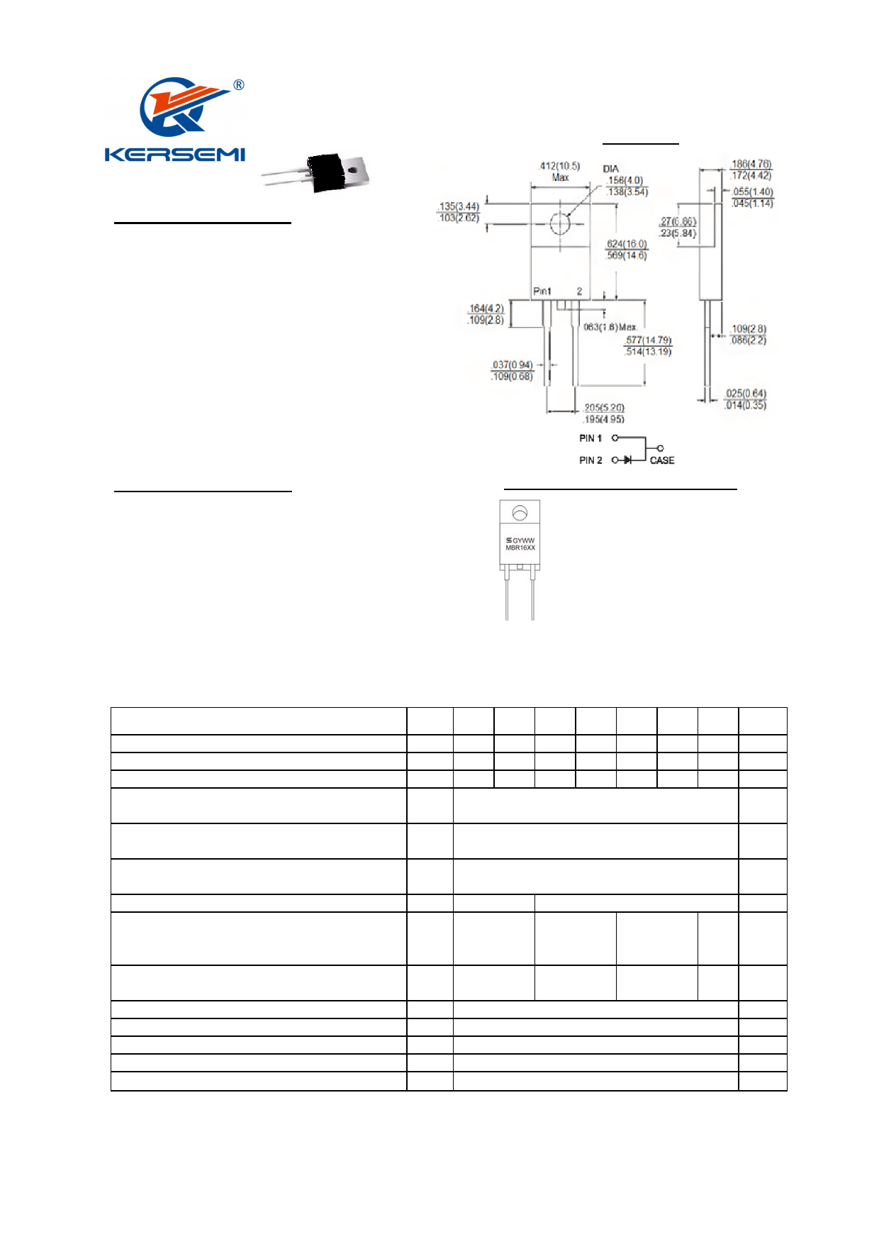
MBR1635 - MBR16150
16.0 AMPS. Schottky Barrier Rectifiers
TO-220AC
Features
Plastic material used carriers Underwriters
Laboratory Classification 94V-0
Metal silicon junction, majority carrier conduction
Low power loss, high efficiency
High current capability, low forward voltage drop
High surge capability
For use in low voltage, high frequency inverters,
free wheeling, and polarity protection applications
Guard-ring for overvoltage protection
High temperature soldering guaranteed:
260℃/10 seconds, 0.25"(6.35mm) from case
Green compound with suffix "G" on packing
code & prefix "G" on datecode
Mechanical Data
Cases: JEDEC TO-220AC molded plastic body
Terminals: Pure tin plated, lead free, solderable
per MIL-STD-750, Method 2026
Polarity: As marked
Mounting position:Any
Mounting torque: 5 in. - lbs, max
Weight: 1.86 grams
Dimensions in inches and (millimeters)
Marking Diagram
MBR16XX = Specific Device Code
G
= Green Compound
Y
= Year
WW
= Work Week
Maximum Ratings and Electrical Characteristics
Rating at 25 ℃ ambient temperature unless otherwise specified.
Single phase, half wave, 60 Hz, resistive or inductive load.
For capacitive load, derate current by 20%
Type Number
Maximum Recurrent Peak Reverse Voltage
Symbol
MBR
1635
VRRM
35
Maximum RMS Voltage
VRMS
24
Maximum DC Blocking Voltage
VDC
35
MBR
1645
45
31
45
MBR
1650
50
35
50
MBR
1660
60
42
60
MBR
1690
90
63
90
MBR
16100
100
70
100
MBR
16150
150
105
150
Units
V
V
V
Maximum Average Forward Rectified Current
IF(AV)
16
A
Peak Repetitive Forward Current
(Rated VR, Square Wave, 20KHz)
Peak Forward Surge Current, 8.3 ms Single Half Sine-
wave Superimposed on Rated Load (JEDEC method)
Peak Repetitive Reverse Surge Current (Note 1)
Maximum Instantaneous Forward Voltage at: (Note 2)
IF=16A, TA=25℃
IF=16A, TA=125℃
Maximum Ilstantaneous Reverse Current @ T A=25 ℃
at Rated DC Blocking Voltage
@ T A=125 ℃
Voltage Rate of Change (Rated V R)
Typical Junction Capacitance
Maximum Typical Thermal Resistance
Operating Junction Temperature Range
Storage Temperature Range
IFRM
IFSM
IRRM
VF
IR
dV/dt
Cj
RθJC
TJ
TSTG
1.0
0.63
0.57
0.5
15
32
150
0.5
0.75
0.85
0.65
0.75
0.5
0.3
10
7.5
10,000
500
3
- 65 to + 150
- 65 to + 175
A
A
A
0.95
0.92
0.1
5
V
mA
mA
V/uS
pF
OC/W
OC
OC
www.kersemi.com
Share Link: 