M69AW024BE Ver la hoja de datos (PDF) - STMicroelectronics
Número de pieza
componentes Descripción
Fabricante
M69AW024BE Datasheet PDF : 25 Pages
| |||
M69AW024BE
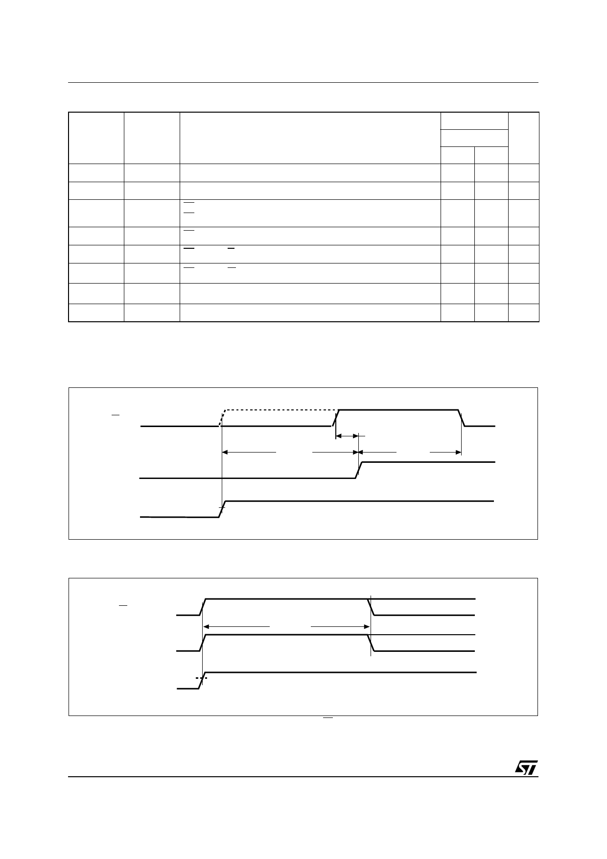
Table 9. Standby, Power-Down and Power-Up AC Parameters
Symbol
Alt.
Parameter
tCLEL
tCSP
E2 Low Setup Time for Power Down Entry
tELCH
tC2LP E2 Low Hold Time after Power Down Entry
tCHEL(1)
tCHH
E1 High Hold Time following E2 High after Power-Down Exit
E1 High Hold Time following E2 High after Power-Up
tEHCH
tCHS
E1 High Setup Time following E2 High after Power-Down Exit
tEHGH
tCHOX E1 High to G Invalid Time for Standby Entry
tEHWH(2)
tCHWX E1 High to W Invalid Time for Standby Entry
tτ(3)
tτ
Input Transition Time
tEHCH2
tC2LH
Power-Up Time
Note: 1. Applicable both to Power-Down and Power-Up.
2. Some data might be written into any address location if tEHWL (min) is not satisfied.
3. The Input Transition Time used in AC measurements is 5ns.
4. TBD = to be defined.
M69AW024BE
–60
Unit
Min Max
10
ns
80
ns
300
µs
0
ns
10
ns
10
ns
1
25
ns
50
µs
Figure 16. Power-up Mode AC Waveforms - 1
E1
tEHCH2
E2
VCC
0V
VCC min
Note: tEHCH2 is defined from VCC reaching VCC(min).
Figure 17. Power-up Mode AC Waveforms - 2
tEHCH
tCHEL
AI07740b
E1
E2
VDD
tEHEL
VDDmin
Note: tCHEL is defined from VCC reaching VCC(min) and applicable both for E1 and E2 signals.
AI09945
20/25
Share Link: 