LA4805 Ver la hoja de datos (PDF) - SANYO -> Panasonic
Número de pieza
componentes Descripción
Fabricante
LA4805 Datasheet PDF : 17 Pages
| |||
LA4805V
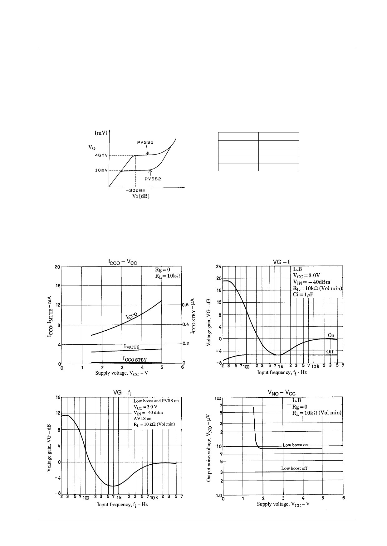
• As shown in the figure above, PVSS is designed so that PVSS is operated and turned on by inputting to pin 19 the
mixed power outputs through 15 kΩ resistors. When this input is grounded, PVSS is turned off.
• PVSS switching can be changed by an IC internal 30 kΩ resistor and an external (150 kΩ) resistor. When this
function is used, VO is set to 45 mV by passing the mixed signal through a 150 kΩ resistor at PVSS1, and is set to
10 mV by passing the mixed signal through only the 0.22 µF capacitor at PVSS2. (Detailed data is provided
separately.)
• The graph below gives a simplified view of the Vi-VO characteristics and the output VO when RP is varied.
RP
50 kΩ
100 kΩ
150 kΩ
200 kΩ
VO
25 mV
35 mV
46 mV
56 mV
No. 4469-13/17
Share Link: 