IMP803 Ver la hoja de datos (PDF) - IMP, Inc
Número de pieza
componentes Descripción
Fabricante
IMP803 Datasheet PDF : 8 Pages
| |||
IMP803
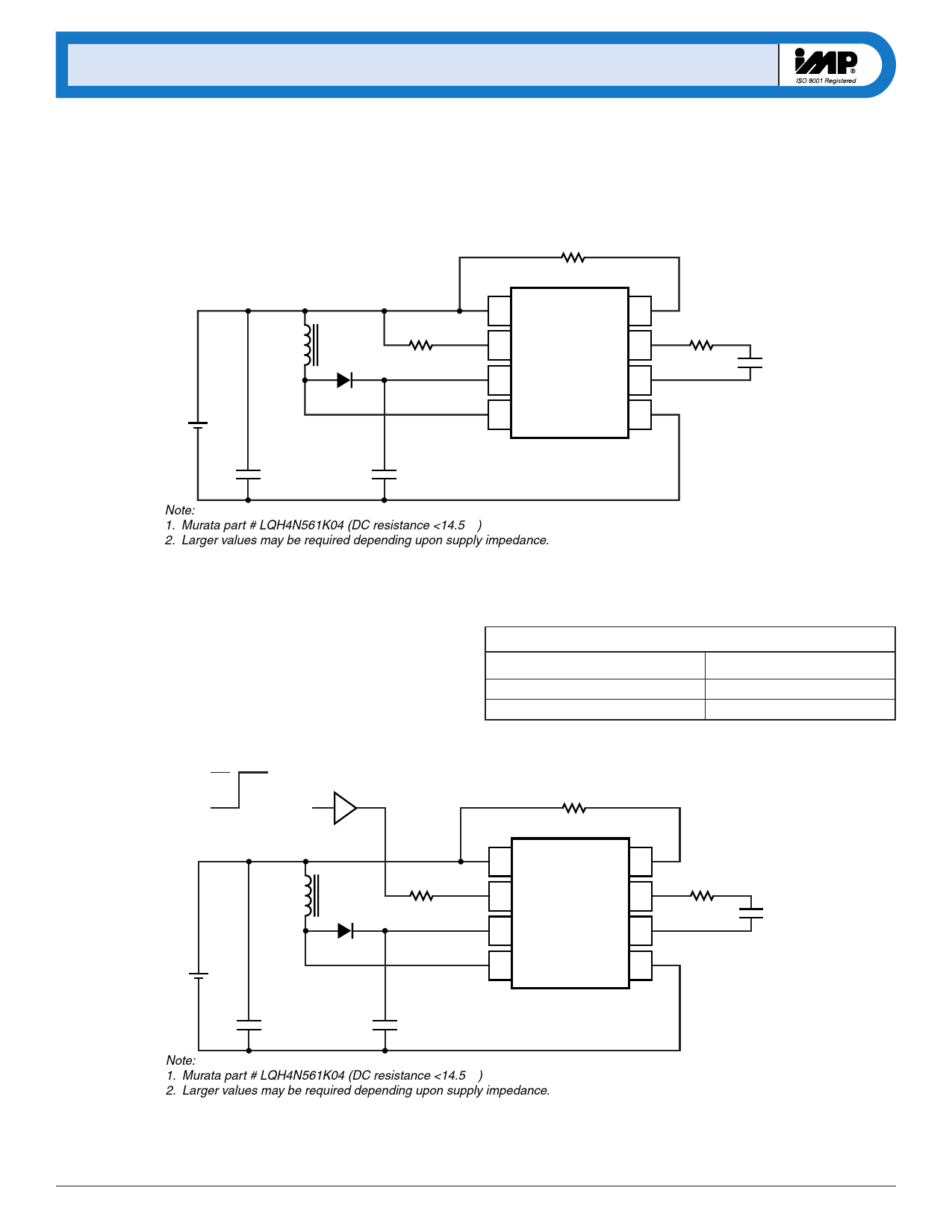
Test and Application Circut, 6.0V
At higher input voltage levels, the IMP803 will drive large EL
lamps. Figure 3 shows a 6.0V circuit configuration that will drive
a 10 square-inch lamp.
2MΩ
REL
+
VIN = 6.0V –
560µH1 L
1N4148
330kΩ
RSW
0.1µF2
0.1µF
CS
100V
1 VDD
REL-OSC 8
2 RSW-OSC
VA 7
3 CS
VB 6
4 LX
GND 5
2kΩ
RCL
IMP803
Note:
1. Murata part # LQH4N561K04 (DC resistance <14.5 Ω)
2. Larger values may be required depending upon supply impedance.
Figure 3. 6.0V Application
10 in2 lamp
803_11.eps
Enable/Disable Operation
Figure 4 shows that the IMP803 can be enabled via a logic gate that
connects RSW to VDD, and disabled by connecting it to ground.
Enable/Disable Table
RSW Connection
VDD
GND
IMP803 State
Enabled
Disabled
ON = VDD
CMOS
Gate
REL
OFF = 0V
1 VDD
REL-OSC 8
RSW
RCL
L1
2 RSW-OSC
VA 7
+
VIN –
1N4148
0.1µF2
0.1µF
CS
100V
3 CS
4 LX
VB 6
GND 5
IMP803
Note:
1. Murata part # LQH4N561K04 (DC resistance <14.5 Ω)
2. Larger values may be required depending upon supply impedance.
Figure 4. Enable/Disable Operation
EL lamp
803_12.eps
6
408-432-9100/www.impweb.com
© 2000 IMP, Inc.
Share Link: 