HTRM800 Ver la hoja de datos (PDF) - Philips Electronics
Número de pieza
componentes Descripción
Fabricante
HTRM800 Datasheet PDF : 20 Pages
| |||
Philips Semiconductors
HITAG long range reader module
hardware
7 FUNCTIONAL DESCRIPTION
handbook, full pagewidth
POWER
SUPPLY
HOST
SYSTEM
HTRM800
Product specification
HTRM800 family
HITAG 1
transponders
antenna
I/O FUNCTIONS
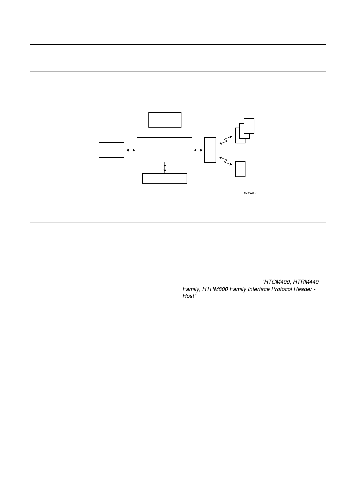
Fig.3 System overview.
HITAG 2
transponder
MGU419
7.1 System overview
The HITAG long range reader module (see Fig.3) is a part
of a complete Radio Frequency Identification (RFID)
system which consists of:
• Transponders
• Antenna
• Host system
• I/O functions
• Power supply.
7.1.1 TRANSPONDERS
The HTRM800 can communicate with transponders based
on Philips HITAG 1 and HITAG 2.
7.1.2 ANTENNA
The antenna is an important part of the HITAG long range
system. The antenna must provide energy and data
transmission between the reader module and transponder.
7.1.3 HOST SYSTEM
The connection to the host system (e.g. microcontroller
or PC) is a serial interface on RS232 level for data
transmission.
7.1.4 I/O FUNCTIONS
One line of the HTRM800 is wired as input from e.g. a
switch and one line as output to drive a LED.
7.1.5 POWER SUPPLY
The HTRM800 must be supplied from an external power
supply with +15 V and −15 V (see Section 10.3).
7.2 Reader module software
Software command names mentioned in this data sheet
are fully described in document “HTCM400, HTRM440
Family, HTRM800 Family Interface Protocol Reader -
Host”.
7.3 Reader module hardware
7.3.1 MICROCONTROLLER
The microcontroller is placed on the HITAG core module
(see Fig.1) and processes the protocol for the
communication between the transponders and the reader
module. The interface signals are converted so that the
transponders are able to process them and the outgoing
signals from the transponders are converted into
interface-compatible signals.
The second essential microcontroller function is its control
function. The microcontroller activates and deactivates the
transmitter and switches the receiver between the modes
for the different transponders reception.
Additional functions of the microcontroller are controlling
the standby mode of the amplifier, detection of detuned or
broken antennas (antenna malfunction) and controlling of
the input and output for general purpose.
2001 Oct 04
6
Share Link: 