TC7135CLI Ver la hoja de datos (PDF) - TelCom Semiconductor Inc => Microchip
Número de pieza
componentes Descripción
Fabricante
TC7135CLI Datasheet PDF : 13 Pages
| |||
4-1/2 DIGIT
ANALOG-TO-DIGITAL CONVERTER
1
is disabled for one clock pulse at the beginning of the
reference integrate (deintegrate) phase. This one-count
delay compensates for the delay of the zero-crossing flip-
flop, and allows the correct number to be latched into the
display. Similarly, a one-count delay at the beginning of
auto-zero gives an overload display of 0000 instead of 0001.
No delay occurs during signal integrate, so true ratiometric
readings result.
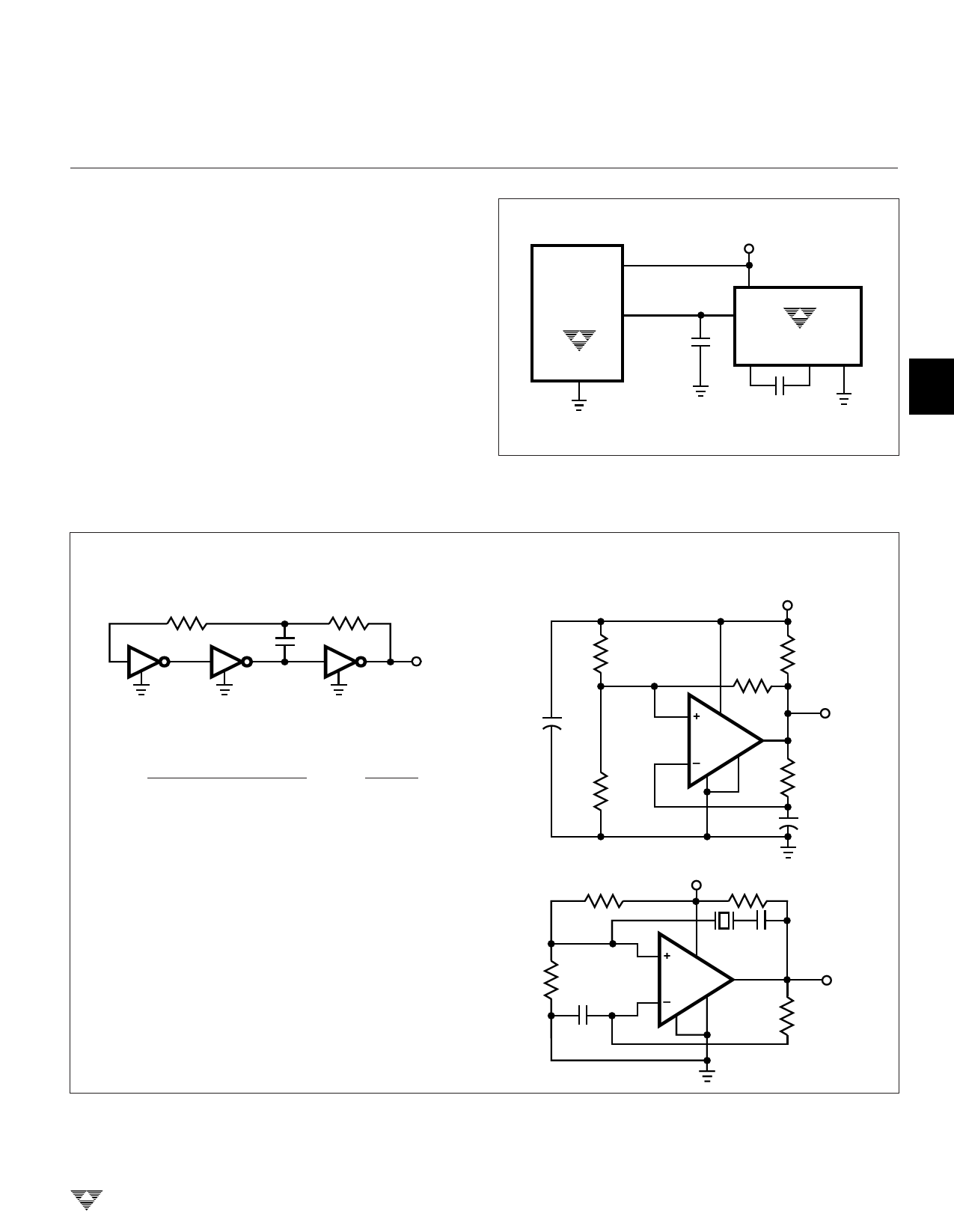
Generating a Negative Supply
A negative voltage can be generated from the positive
supply by using a TC7660. (See Figure 9.)
TC7135
+5V
2
V+ 11
8
V – 1 (–5V)
5
10 µF
TC7660
+
TC7135
24
4
+2 3
3
10 µF
Figure 9. Negative Supply Voltage Generator
TYPICAL APPLICATIONS
RC Oscillator Circuit
R2
C
R1
fO
GATES ARE 74C04
1. fO ≈
1
2 C[0.41 RP + 0.70 R1]
, RP =
R1 R2
R1 + R2
a. If R = R1 = R2, f ≅ 0.55/RC
b. If R2 >> R1, f ≅ 0.45/R1C
c. If R2 << R1, f ≅ 0.72/R1C
2. Examples:
a. f = 120 kHz, C = 420 pF
R1 = R2 ≈ 10.9 kΩ
b. f = 120 kHz, C = 420 pF, R2 = 50 kΩ
R1 = 8.93 kΩ
c. f = 120 kHz, C = 220 pF, R2 = 5 kΩ
R1 = 27.3 kΩ
4
Comparator Clock Circuit
+5V
0.22 µF
16 kΩ
1 kΩ
56 kΩ
2+ 8
LM311 7
5
VOUT
3–
1
4
30 kΩ
16 kΩ
390 pF
6
R2
100 kΩ
+5V R4
2 kΩ
2+ 6
C2
10 pF
R2
100 kΩ
C1
0.1 µF
LM311 7
3–
4
1
VOUT
R3
7
50 kΩ
TELCOM SEMICONDUCTOR, INC.
8
3-123
Share Link: 