TA2022 Ver la hoja de datos (PDF) - Tripath Technology Inc.
Número de pieza
componentes Descripción
Fabricante
TA2022
Tripath Technology Inc.

TA2022 Datasheet PDF : 31 Pages
| |||
Tripath Technology, Inc. - Technical Information
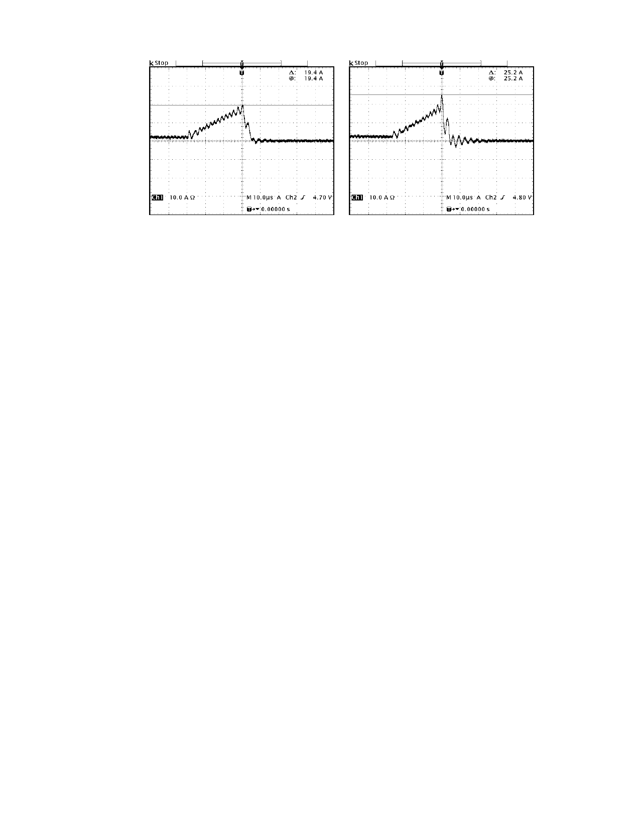
Figure 6: Short circuit load current with unsaturated toroidal inductor and
saturated bobbin Inductor (shielded)
Output Filter Design
Tripath amplifiers generally have a higher switching frequency than PWM implementations allowing
the use of higher cutoff frequency filters, reducing the load dependent peaking/drooping in the 20kHz
audio band. This is especially important for applications where the end customer may attach any
speaker to the amplifier (as opposed to a system where speakers are shipped with the amplifier),
since speakers are not purely resistive loads and the impedance they present changes over
frequency and from speaker model to speaker model. An RC network, or “zobel” (RZ, CZ) must be
placed at the filter output to control the impedance “seen” by the TA2022. The TA2022 works well
with a 2nd order, 107kHz LC filter with LO = 10uH and CO = 0.22uF and RZ = 6.2ohm/2W and CZ =
0.22uF. Some applications may require a more aggressive filter to reduce out of band noise. Below
are some proven filter combinations:
- 49.5kHz 2nd order filter
LO = 22uH
CO = .47uF
RZ = 8Ω
CZ = .47uF
- 33.6kHz 2nd order filter
LO = 33uH
CO = .68uF
RZ = 6.2Ω
CZ = .68uF
- 65kHz 4th order filter
LO1 = 15uH
CO1 = 1uF
LO2 = 10uH
CO2 = .22uF
RZ = 10Ω
CZ = .47uF
Output inductor selection is a critical design step. The core material and geometry of the output filter
inductor affects the TA2022 distortion levels, efficiency, over-current protection, power dissipation and
EMI output. The inductor should have low loss at 700kHz with 80Vpp. It should be reiterated that
regardless of the systems maximum operating current, a 10A rating is required to ensure that peak
current conditions will not cause the inductor to saturate. During a short circuit event the inductor
current increases very quickly in a saturated core (see figure 6), compromising the current protection
scheme. A 10A rating is sufficient to ensure that current increases through the inductor are linear, and
provides a safety margin for the TA2022. There are two types of inductors available in the 10A range
that offers some EMI containment: they are the toroidal type and the bobbin (shielded) type inductor.
In bobbin construction, a ferrite shield is placed around the core of a bobbin inductor to help contain
radiated emissions. This shield can reduce the amount of energy the inductor can store in the core by
reducing the air gap, which can lower the peak current capability of the inductor. Typically, a 7-10A
shielded bobbin inductor will not have the peak current capability necessary to ensure that the core
21
TA2022 – KLI/1.2/07-04
Share Link: