TK65930MTL/C5 Ver la hoja de datos (PDF) - Toko America Inc
Número de pieza
componentes Descripción
Fabricante
TK65930MTL/C5 Datasheet PDF : 16 Pages
| |||
TK6593x
APPLICATION INFORMATION
EL LAMP INTENSITY CONTROL APPLICATION
In driving EL lamp panels, it is sometimes desirable to be able to adjust the intensity of the EL lamp. The TK6593x can
be used in such an application. By reducing the voltage supplied to the VCC pin of the TK6593x, one can reduce the peak
current regulation point of the IC. This translates into a reduction in the peak to peak output voltage across the EL panel,
which reduces the intensity of the light being emitted from the EL lamp.
By decreasing the input voltage to the VCC pin from 2.9 V to 2.1 V, the peak current regulation point will be reduced about
53 mA. This correlates to about a 2/3 reduction in the peak to peak voltage appearing across the EL lamp panel.
The VCC pin only takes 200 µA max. when the EL driver is in operation. Therefore, it can normally be controlled by logic
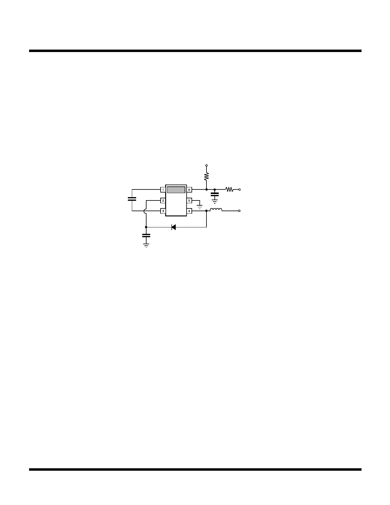
power level signals. One way of accomplishing this with two digital logic signals is shown in Figure 4.
R1 = 1.5 kΩ
R2 = 3.0 kΩ
C2 = 10 nF
3 V ~ 1 mA source
R1
1.5 k
CEL
20 nF
EL +
HV
EL -
VCC
GND
C2
10 nF
IND
L1
3 V PWM
10% to 90%
200 KHz to 300 KHz
R2
~ 1 mA sink
3k
Vpower
1.8 to 7 V
C1
D1
100 nF
FIGURE 4: INTENSITY CONTROL APPLICATION
NOISE CONSIDERATIONS
There are two specific noise types relevant to the user when it comes to choosing EL Drivers: the Audio Noise and the
Electromagnetic Interference (EMI) Noise.
The EMI Noise would most likely come from the boost converter section of the EL Driver circuit. The Toko EL Driver has
specifically been designed to address this issue.
The device runs at a fixed frequency and the frequency is controlled tightly in order to avoid interference.
Furthermore, the panel frequency is forced to be a 128 submultiple of the boost frequency avoiding any type of beating
frequencies.
By choosing shielded coils, the EMI noise problem can further be reduced.
The Audio Noise can come from several components which make up the system.
The coil, if operated in the audio range would be a source of noise. The Toko EL Driver was carefully designed to give
the user the choice of 10 frequencies such that the coil frequency will always be above audio range. Since the device
operates at a fixed frequency in discontinuous conduction mode, there are no possible submultiples which would cause
audible noise.
The filter capacitor can be a source of audio noise. Furthermore, depending on how this cap is mounted, the mounting
can act as an amplifier (as a speaker box). Certain ceramic caps driven from a high voltage source as in the EL Driver
case, demonstrate a PIEZOELECTRIC effect which is distinguishable in the Audio Range.
Other types of caps, such as film type do not denote an audio noise.
The panel itself, being operated well into the Audio Range (175 Hz to 400 Hz) and of a capacitive nature driven from high
voltage may also display Audible Noise. Mounting of this panel can enhance or diminish this natural effect of the panel.
Page 14
May 2000 TOKO, Inc.
Share Link: 