28F008C3 Ver la hoja de datos (PDF) - Intel
Número de pieza
componentes Descripción
Fabricante
28F008C3 Datasheet PDF : 59 Pages
| |||
3 VOLT ADVANCED+ BOOT BLOCK
E
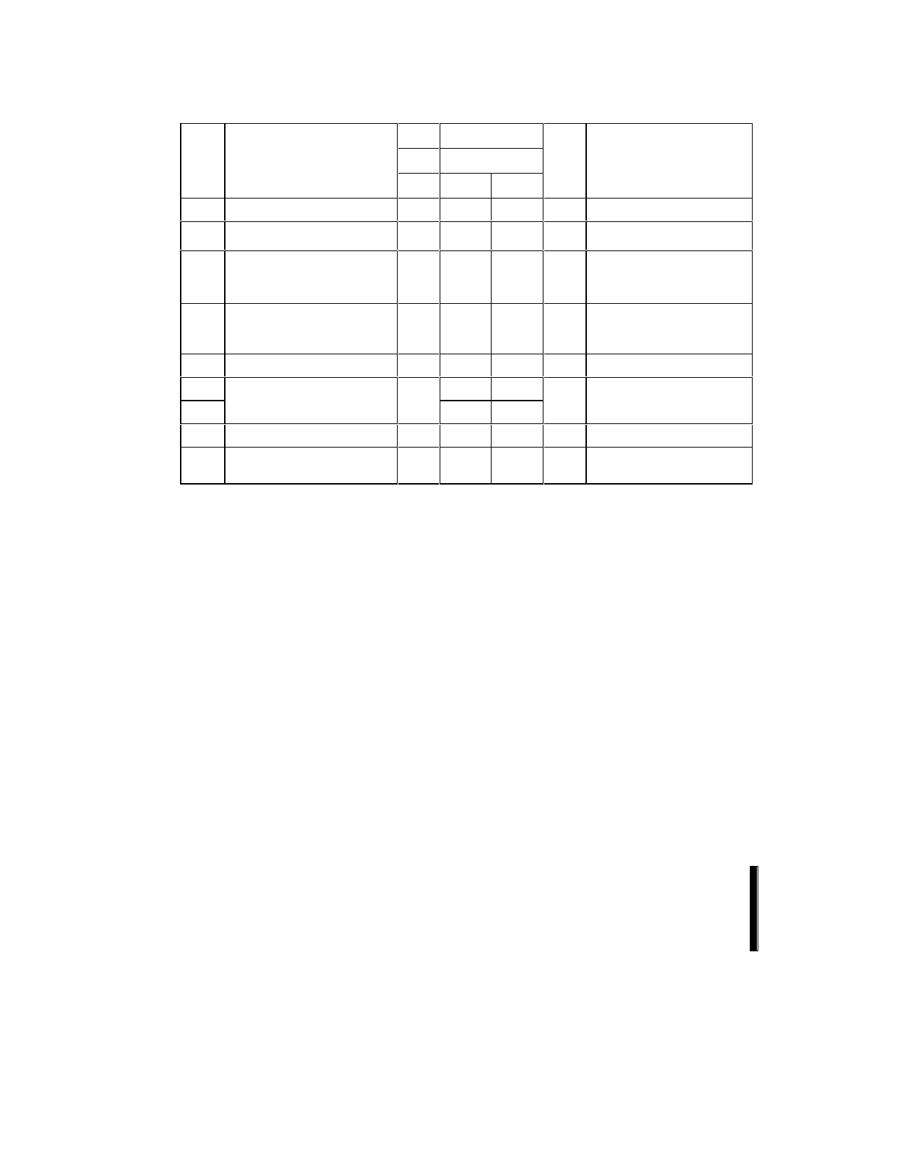
4.4 DC Characteristics, Continued
VCC
2.7 V–3.6 V
VCCQ 2.7 V–3.6 V
Sym
Parameter
Note Min Max Unit
Test Conditions
VIL Input Low Voltage
VIH Input High Voltage
VOL Output Low Voltage
-0.4
0.4
VCCQ -
0.4 V
7
-0.10 0.10
VOH Output High Voltage
7
VCCQ -
0.1 V
VPPLK VPP Lock-Out Voltage
3
VPP1 VPP during Program / Erase
3
VPP2 Operations
3,6
VLKO VCC Prog/Erase Lock Voltage
VLKO2 VCCQ Prog/Erase Lock
Voltage
1.65
11.4
1.5
1.2
1.0
3.6
12.6
V
V
V VCC = VCCMin
VCCQ = VCCQMin
IOL = 100 µA
V VCC = VCCMin
VCCQ = VCCQMin
IOH = –100 µA
V Complete Write Protection
V
V
V
NOTES:
1. All currents are in RMS unless otherwise noted. Typical values at nominal VCC, TA = +25 °C.
2. ICCES and ICCWS are specified with device de-selected. If device is read while in erase suspend, current draw is sum of
ICCES and ICCR. If the device is read while in program suspend, current draw is the sum of ICCWS and ICCR.
3. Erase and Program are inhibited when VPP < VPPLK and not guaranteed outside the valid VPP ranges of VPP1 and VPP2.
4. Sampled, not 100% tested.
5. Automatic Power Savings (APS) reduces ICCR to approximately standby levels in static operation (CMOS inputs).
6. Applying VPP = 11.4 V–12.6 V during program/erase can only be done for a maximum of 1000 cycles on the main blocks
and 2500 cycles on the parameter blocks. VPP may be connected to 12 V for a total of 80 hours maximum. See Section
3.4 for details.
7. The test conditions VCCMax, VCCQMax, VCCMin, and VCCQMin refer to the maximum or minimum VCC or VCCQ voltage
listed at the top of each column.
28
PRODUCT PREVIEW
Share Link: 