AN725 Ver la hoja de datos (PDF) - Silicon Laboratories
Número de pieza
componentes Descripción
Fabricante
AN725 Datasheet PDF : 28 Pages
| |||
AN725
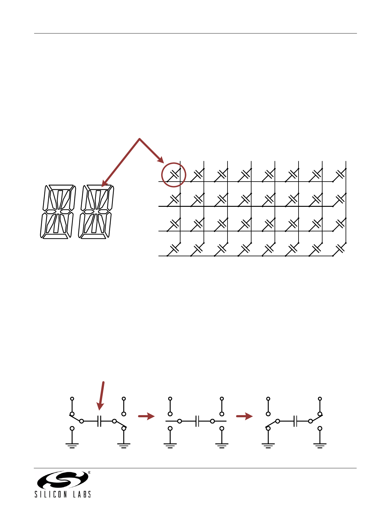
5.4. LCD
For applications that use the LCD0 module, the SiM3L1xx devices have several features that help reduce power
consumption.
5.4.1. Segment Resetting
Each segment of an LCD can be modeled as a capacitor in the order of tens of pF. A typical load current is 1 nA per
segment per pF, so a 160-segment LCD with 50 pF per segment can draw 8 µA of load current. The SiM3L1xx
devices include a segment resetting feature to reduce this load current. Figure 7 illustrates the basic architecture
model of an LCD.
Segment
SEG0 SEG1 SEG2 SEG3 SEG4 SEG5 SEG6 SEG7
COM0
COM1
COM2
COM3
Figure 7. LCD Model
LCD segments are energized (i.e., turn opaque) by ac potential waveforms between the segment and the common
signal for that segment. These waveforms transition between 0 and 3 V, for example, which results in an amplitude
of –3 to 3 V on the segment, depending on the phase of the segment and common waveforms. Figure 9 shows an
example of the common waveforms for 4-mux mode.
To turn on a segment, the controller drives the segment to 3 V or 0 V when the common is driven to 0 V or 3 V,
which leads to ±3 V on the segment. To turn a segment off, the controller drives the segment to 1 V or 2 V when the
common signal is 0 V or 3 V, which leads to ±1 V on the segment.
Most LCD controllers transition directly from the most positive amplitude (3 V) to the most negative amplitude
(–3 V), as shown in Figure 8. This behavior leads to extra charge being pulled from the battery, since the battery
must drive a 6 V transition overall.
Segment
3V
3V
3V
3V
3V
3V
+3 V
+3 V
-3 V
Figure 8. Traditional LCD Segment Transition
Rev. 0.1
21
Share Link: 