AD9984AKSTZ-170 Ver la hoja de datos (PDF) - Analog Devices
Número de pieza
componentes Descripción
Fabricante
AD9984AKSTZ-170 Datasheet PDF : 44 Pages
| |||
AD9984A
Negative target codes are included to duplicate a feature that is
present with manual offset adjustment. The benefit that is
mimicked is the ability to easily adjust brightness on a display. By
setting the target code to a value that does not correspond to the
ideal ADC range, the end result is an image that is brighter or
darker. A target code higher than ideal results in a brighter image,
whereas a target code lower than ideal results in a darker image.
The ability to program a target code offers a large degree of
freedom and flexibility. Although all channels are set to either 1
or 512 in most cases, the flexibility to select other values makes
it possible to insert intentional skews between channels. It also
allows the ADC range to be skewed so that voltages outside of
the normal range can be digitized. For example, setting the
target code to 40 allows the sync tip, which is normally below
black level, to be digitized and evaluated.
The internal logic for the auto-offset circuit requires 16 data
clock cycles to perform its function. This operation is executed
immediately after the clamping pulse. Therefore, it is important
to end the clamping pulse signal at least 16 data clock cycles
before active video. This is true whether using the AD9984A
internal clamp circuit or an external CLAMP signal. The auto-
offset function can be programmed to run continuously or on a
one-time basis (see the 0x2C—Bit[4] Auto-Offset Hold
section). In continuous mode, the update frequency can be
programmed (Register 0x1B, Bits[4:3]). Continuous operation
with updates every 192 Hsyncs is recommended.
Guidelines for basic auto-offset operation are shown in Table 6
and Table 7.
Table 6. RGB Auto-Offset Register Settings
Register
Value Comments
0x0B
0x00 Sets red target to 4.
0x0C
0x80 Must be written.
0x0D
0x00 Sets green target to 4.
0x0E
0x80 Must be written.
0x0F
0x00 Sets blue target to 4.
0x10
0x80 Must be written.
0x18, Bits[3:1] 000
Sets red, green, and blue channels to
ground clamp.
0x1B, Bits[5:3] 110
Selects update rate to every 192
clamps and enables auto-offset.
Table 7. YPbPr Auto-Offset Register Settings
Register
Value Comments
0x0B
0x40 Sets Pr (red) target to 512.
0x0C
0x00 Must be written.
0x0D
0x00 Sets Y (green) target to 4.
0x0E
0x80 Must be written.
0x0F
0x40 Sets Pb (blue) target to 512.
0x10
0x00 Must be written.
0x18, Bits[3:1] 101
Sets Pb, Pr to midscale clamp and Y to
ground clamp.
0x1B, Bits[5:3] 110
Selects update rate to every 192
clamps and enables auto-offset.
Automatic Gain Matching
The AD9984A includes circuitry to match the gains between
the three channels to within 1% of each other. Matching the
gains of each channel is necessary to achieve good color balance
on a display. On products without this feature, gain matching is
achieved by writing software that evaluates the output of each
channel, calculates gain mismatches, and then writes values to
the gain registers of each channel to compensate. With the auto
gain matching function, this software routine is no longer needed.
To activate auto gain matching, set Register 0x3C, Bits[2:0] to 110.
Auto gain matching has similar timing requirements to auto
offset. It requires 16 data clock cycles to perform its function,
starting immediately after the end of the clamp pulse. Unlike
auto offset, auto gain matching does not require that these
16 clock cycles occur during the back porch reference time,
although it is recommended. During auto gain matching
operation, the data outputs of the AD9984A are frozen (held at
the value they had just prior to operation). The auto gain
matching function can be programmed to run continuously or
on a one-time basis (see the 0x3C—Bit[3] Auto Gain Matching
Hold section). In continuous mode, the update frequency can
be programmed (Register 0x1B, Bits[4:3]). Continuous
operation with updates every 192 Hsyncs is recommended.
SYNC-ON-GREEN
The sync-on-green inputs (SOGIN0, SOGIN1) operate in two
steps. First, they set a baseline clamp level off the incoming
video signal with a negative peak detector. Second, they set the
voltage level of the SOG slicer’s comparator (Register 0x1D,
Bits[7:3]) with a variable trigger level to a programmable level
(typically 128 mV) above the negative peak. Each sync-on-
green input must be ac-coupled to the green analog input
through its own capacitor. The value of the capacitor must be
1 nF ± 20%. If sync-on-green is not used, this connection is not
required. The sync-on-green signal always has negative polarity.
47nF
47nF
47nF
1nF
RAIN
BAIN
GAIN
SOGIN
Figure 5. Typical Input Configuration
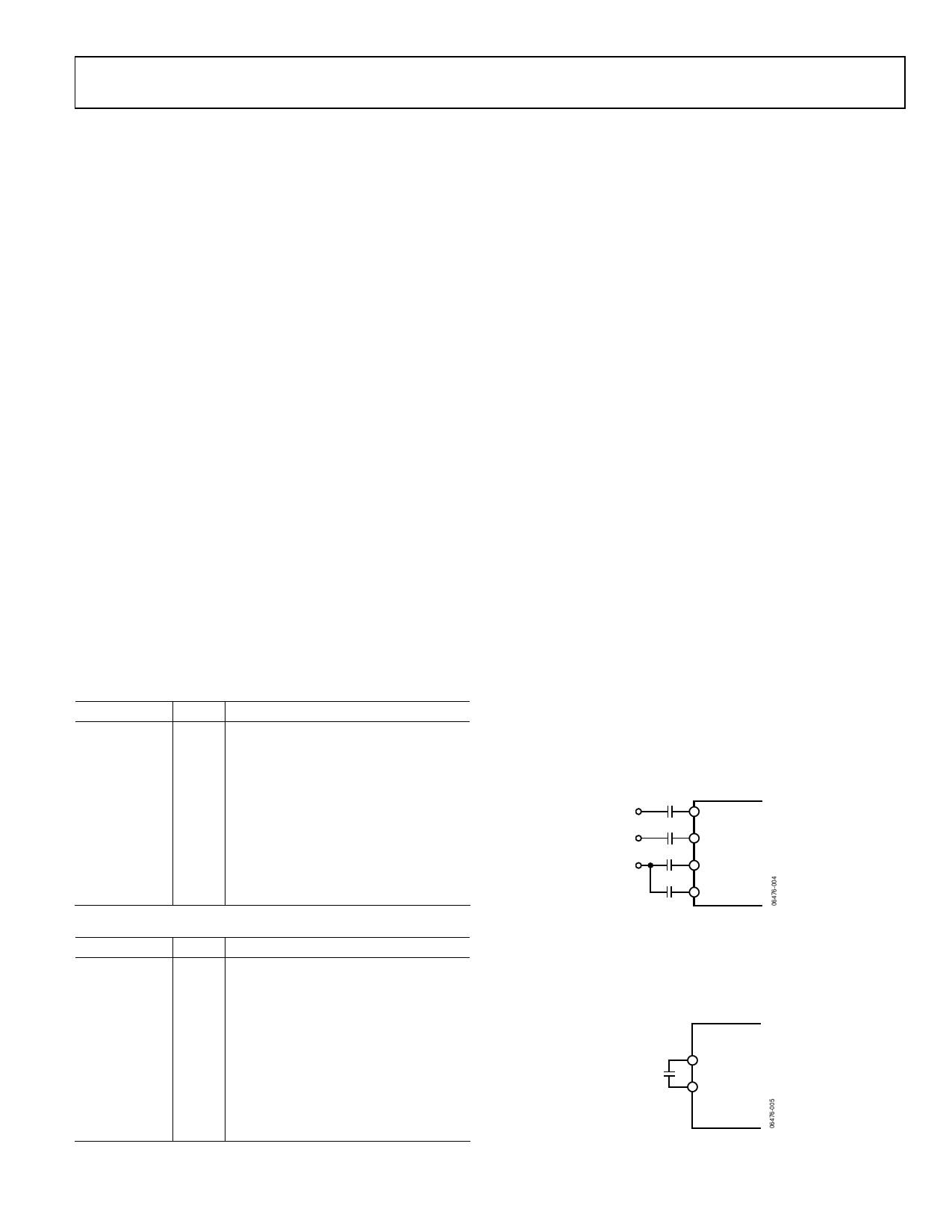
REFERENCE BYPASSING
REFLO and REFHI are connected to each other by a 10 μF
capacitor (see Figure 6). These references are used by the input
ADC circuitry.
10µF
REFHI
REFLO
Figure 6. Input Amplifier Reference Capacitors
Rev. 0 | Page 13 of 44
Share Link: 