1EDI60I12AF Ver la hoja de datos (PDF) - Infineon Technologies
Número de pieza
componentes Descripción
Fabricante
1EDI60I12AF Datasheet PDF : 22 Pages
| |||
8
Application Notes
1EDI EiceDRIVER™ Compact
Separate output variant for IGBT
Application Notes
8.1
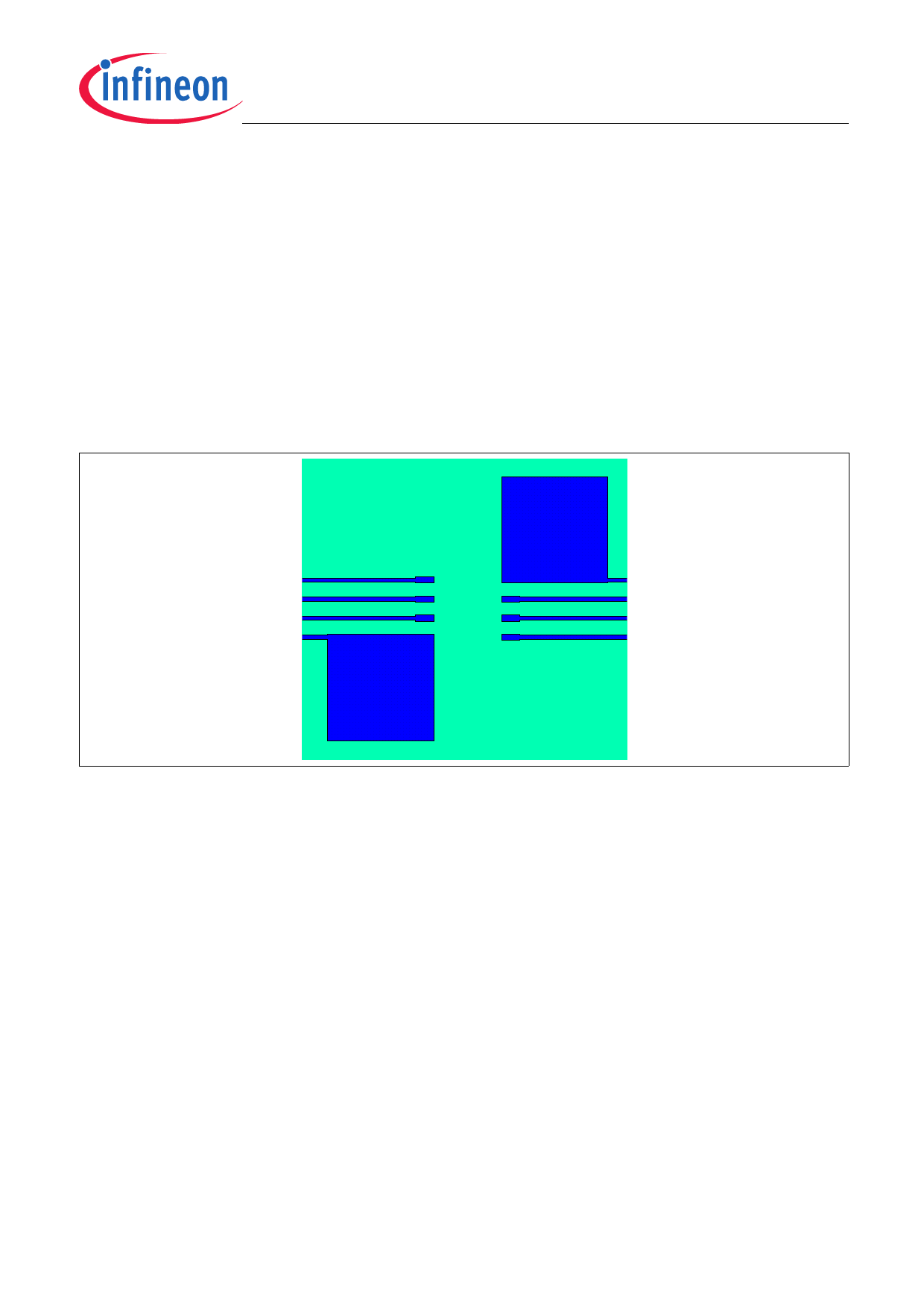
Reference Layout for Thermal Data
The PCB layout shown in Figure 10 represents the reference layout used for the thermal characterisation. Pin 4
(GND1) and pin 8 (GND2) require each a ground plane of 100 mm² for achieving maximum power dissipation. The
Separate output variant for IGBT is conceived to dissipate most of the heat generated through these pins.
The thermal coefficient junction-top (Ψth,jt) can be used to calculate the junction temperature at a given top case
temperature and driver power dissipation:
Tj = Ψth,jt ⋅ PD + Ttop
Figure 10 Reference Layout for Thermal Data (JEDEC 1s0p, 100mm², Copper thickness 35 μm)
8.2
Printed Circuit Board Guidelines
The following factors should be taken into account for an optimum PCB layout.
• Sufficient spacing should be kept between high voltage isolated side and low voltage side circuits.
• The same minimum distance between two adjacent high-side isolated parts of the PCB should be maintained
to increase the effective isolation and to reduce parasitic coupling.
• In order to ensure low supply ripple and clean switching signals, bypass capacitor trace lengths should be kept
as short as possible.
Preliminary Data Sheet
21
Rev. 1.00, 2013-11-20
Share Link: 