IQ18-HPC Ver la hoja de datos (PDF) - SynQor Worldwide Headquarters
Número de pieza
componentes Descripción
Fabricante
IQ18-HPC Datasheet PDF : 28 Pages
| |||
Technical
Specification
IQ18-HPC Family
APPLICATION CONSIDERATIONS
Input system Instability: This condition can occur because
any dc-dc converter appears incrementally as a negative
resistance load. A detailed application note titled “Input
System Instability” is available on the SynQor website which
provides an understanding of why this instability arises, and
shows the preferred solution for correcting it.
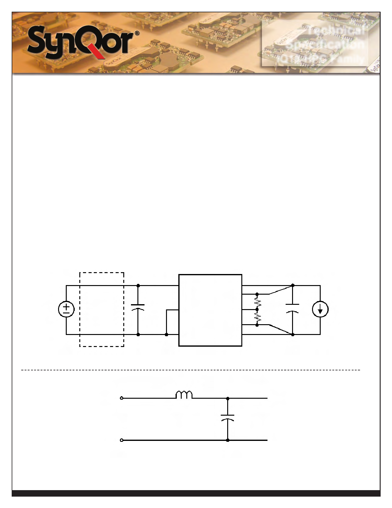
Application Circuits: Figure D provides a typical circuit
diagram which details the input filtering and voltage trimming.
Input Filtering and external Capacitance: Figure E provides
a diagram showing the internal input filter components. This filter
dramatically reduces input terminal ripple current, which otherwise
could exceed the rating of an external electrolytic input capacitor.
The recommended external input capacitance is specified in the
Input Characteristics section on the Electrical Characteristics
page. More detailed information is available in the application
note titled “EMI Characteristics” on the SynQor website.
startup Inhibit Period: The Startup Inhibit Period ensures that
the converter will remain off for approximately 200 ms when it is
shut down for any reason. When an output short is present, this
generates a 5 Hz “hiccup mode,” which prevents the converter
from overheating. In all, there are seven ways that the converter
can be shut down, initiating a Startup Inhibit Period:
• Input Under-Voltage Lockout
• Input Over-Voltage Shutdown
• Output Over-Voltage Protection
• Over Temperature Shutdown
• Current Limit
• Short Circuit Protection
• Turned off by the ON/OFF input
Figure F shows three turn-on scenarios, where a Startup Inhibit
Period is initiated at t0, t1, and t2:
Vin(+)
Vout(+)
Electrolytic
Vsense(+)
External
Capacitor
Rtrim-up
Vin
Input
ON/OFF
Trim
or
Filter
Vsense(_)
Rtrim-down Cload
Iload
Vin(_)
Vout(_)
Figure D: Typical application circuit (negative logic unit, permanently enabled).
L
Vin(+)
C
Vin(_)
Figure E: Internal Input Filter Diagram (component values listed on the specifications page).
Product # IQ18xxxHPCxx
Phone 1-888-567-9596
www.synqor.com
Doc.# 005-005029 Rev. B
04/13/09
Page 26
Share Link: 