VNH3ASP30TR-E Ver la hoja de datos (PDF) - STMicroelectronics
Número de pieza
componentes Descripción
Fabricante
VNH3ASP30TR-E Datasheet PDF : 34 Pages
| |||
Electrical specifications
VNH3ASP30-E
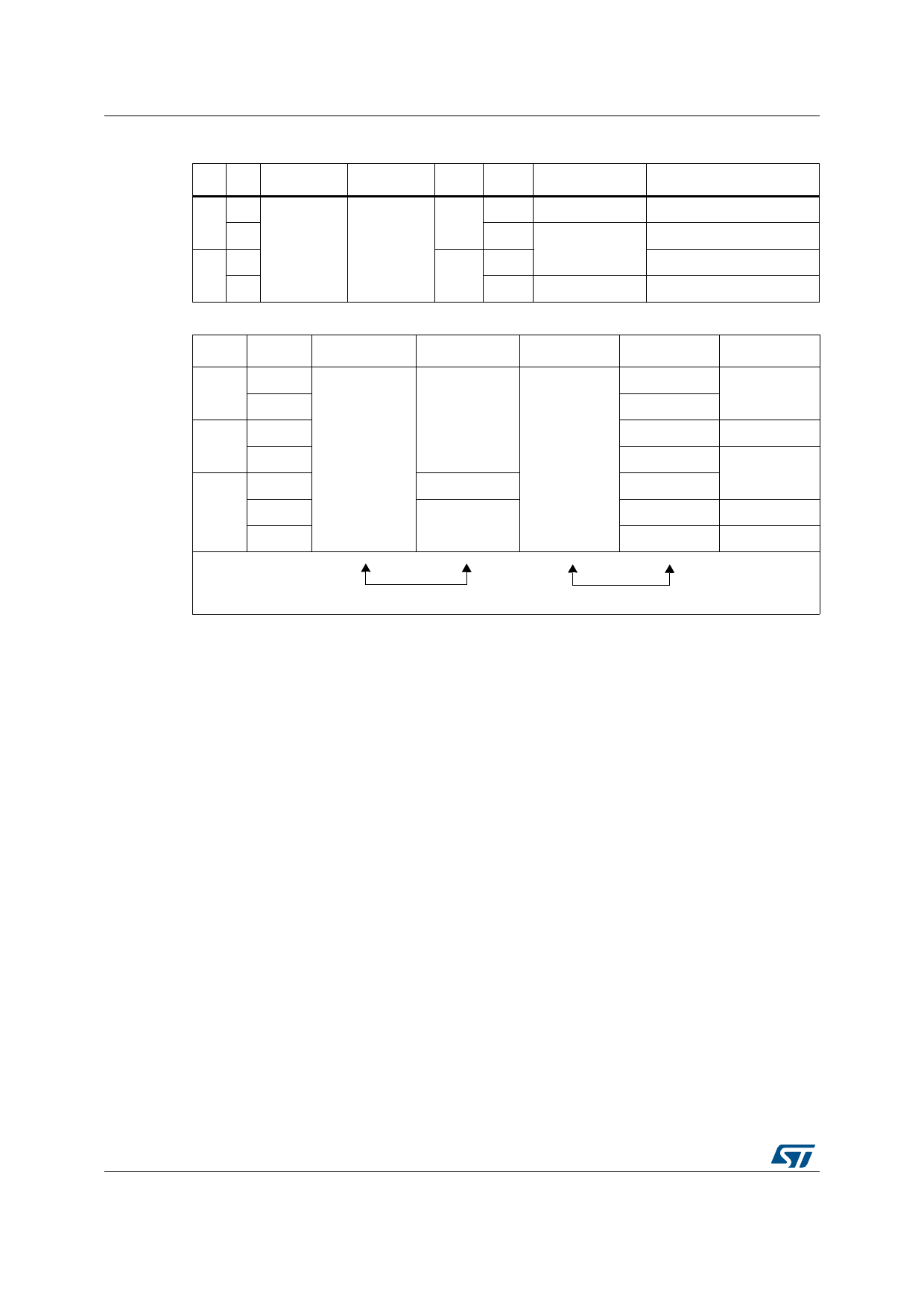
Table 12. Truth table in normal operating conditions
INA INB DIAGA/ENA DIAGB/ENB OUTA OUTB
CS
Operating mode
1
1
0
1
1
0
0
H High Imp.
H
Brake to VCC
L
Clockwise (CW)
1
H ISENSE = IOUT/K Counterclockwise (CCW)
L
L High Imp.
Brake to GND
Table 13. Truth table in fault conditions (detected on OUTA)
INA
INB
DIAGA/ENA DIAGB/ENB
OUTA
OUTB
CS
1
1
0
1
0
0
0
X
H
High Imp.
L
1
H
IOUTB/K
OPEN
L
High Imp.
0
OPEN
X
1
1
0
H
IOUTB/K
L
High Imp.
Note:
Fault Information
Protection Action
Notice that saturation detection on the low side power MOSFET is possible only if the
impedance of the short-circuit from the output to the battery is less than 100m when the
device is supplied with a battery voltage of 13.5V.
14/34
DocID10833 Rev 7
Share Link: 