MAX1672EEE(1997) Ver la hoja de datos (PDF) - Maxim Integrated
Número de pieza
componentes Descripción
Fabricante
MAX1672EEE Datasheet PDF : 12 Pages
| |||
Step-Up/Down DC-DC Converter
in QSOP Package
ABSOLUTE MAXIMUM RATINGS
IN, PS, LX, OUT, PGO to GND ......................... -0.3V to +11.5V
ILIM, ONA, ONB, FB, 3/5,
REF, PGI to GND......................................-0.3V to (VPS + 0.3V)
PGND to GND .......................................................-0.3V to +0.3V
OUT Short Circuit to GND ..........................................Continuous
Output Current ..................................................................350mA
Continuous Power Dissipation (TA = +70°C)
16-Pin QSOP (derate above +70°C by 8.3mW/°C).......667mW
Operating Temperature Range ......................... -40°C to +85°C
Junction Temperature .................................................... +150°C
Storage Temperature Range ........................... -65°C to +160°C
Lead Temperature (soldering, 10sec) ............................ +300°C
Stresses beyond those listed under “Absolute Maximum Ratings” may cause permanent damage to the device. These are stress ratings only, and functional
operation of the device at these or any other conditions beyond those indicated in the operational sections of the specifications is not implied. Exposure to
absolute maximum rating conditions for extended periods may affect device reliability.
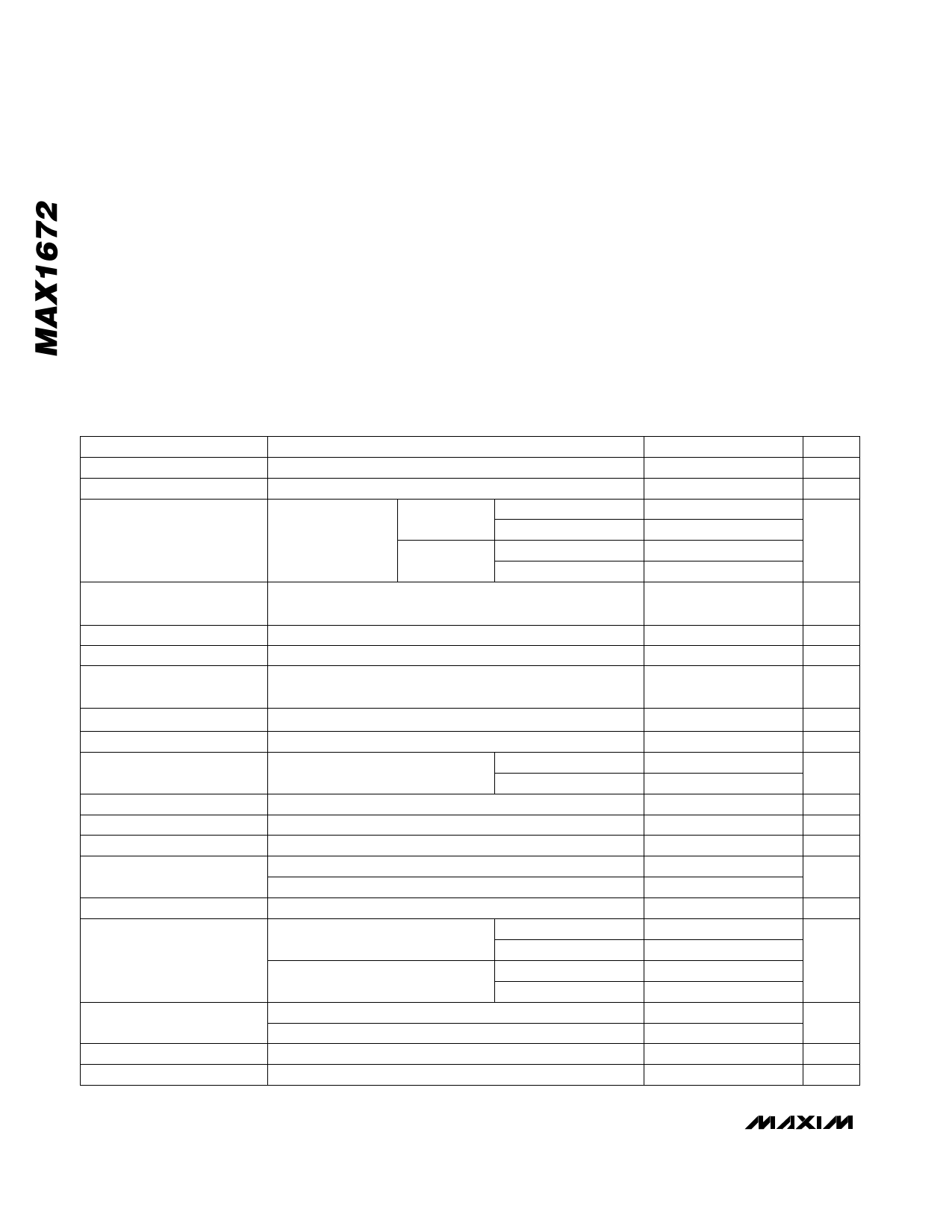
ELECTRICAL CHARACTERISTICS
(VPS = 6V, CREF = 0.1µF, COUT = 4.7µF, TA = -40°C to +85°C, unless otherwise noted. Typical values are at TA = +25°C.) (Note 1)
PARAMETER
Input Voltage
Startup Voltage
Output Voltage
FB = GND,
IOUT = 0mA to
150mA
CONDITIONS
3/5 = GND
3/5 = PS
TA = 0°C to +85°C
TA = -40°C to +85°C
TA = 0°C to +85°C
TA = -40°C to +85°C
MIN TYP MAX UNITS
1.8
11.0 V
0.9
V
4.8
5.2
4.75 5.00 5.25
V
3.17
3.43
3.13 3.30 3.47
Output Voltage Adjustment
Range
1.25
5.5 V
Output Load Regulation
Output Line Regulation
Quiescent Current
Shutdown Quiescent Current
VIN = 2V, 3/5 = GND, FB = GND, IOUT = 10mA to 150mA
VIN = 3V to 5V, 3/5 = GND, IOUT = 100mA
ONA = PS or ONB = GND, current measured into PS pin,
IOUT = 0mA
ONA = GND, ONB = PS, current measured into PS pin
0.003
0.15
85
0.1
%/mA
%/V
125 µA
1
µA
Reference Voltage
IREF = 0mA
FB Voltage
OUT = FB
FB Dual-Mode Trip Threshold
FB Input Current
IN Input Current
LX On-Resistance
LX Leakage Current
Hysteresis = 15mV typical
VFB = 1.3V
VIN = GND to 11V
VPS = 5.5V, ILX = 50mA
VPS = 2.7V, ILX = 50mA
VLX = 11V, ONA = GND, ONB = PS
LX Current Limit
ILIM = GND
ILIM = PS
Output PFET Resistance
Output PFET Leakage Current
Output PFET Current Limit
VPS = 5.5V, IOUT = 50mA
VPS = 2.7V, IOUT = 50mA
VOUT = 0V, ONA = GND, ONB = PS
VPS = 5.5V
TA = 0°C to +85°C
TA = -40°C to +85°C
TA = 0°C to +85°C
TA = -40°C to +85°C
TA = 0°C to +85°C
TA = -40°C to +85°C
1.21 1.25 1.29 V
1.21 1.25 1.29
V
1.20
1.30
70
mV
1
50 nA
3
6
µA
0.6
1.3
Ω
0.9
2.0
0.1
1
µA
0.35
0.5
0.65
0.3
0.5
0.7
A
0.6
0.8
1.0
0.5
0.8
1.1
1.2
2.4
Ω
2.3
4.6
0.1
1
µA
0.35 0.7
1.4 A
2 _______________________________________________________________________________________
Share Link: 