L9935 Ver la hoja de datos (PDF) - STMicroelectronics
Número de pieza
componentes Descripción
Fabricante
L9935 Datasheet PDF : 29 Pages
| |||
Functional description
L9935
next data transfer took place. After detection of a short to VS we suggest to turn off the
corresponding bridge to reduce power dissipation for at least 1ms.
5.5
Diagnosis of a short to VS
During the short current through the sink transistor will rise more rapidly than under normal
load conditions. Reaching a peak current of 1.5 times the maximum PWM current between
typically 2 µs and 5 µs
after turn on will be detected as a short to VS.
Detecting a short the low side transistor will try to turn on again the next 7 trigger pulse of
the oscillator.
Simultaneously the error flag will updated on each pulse.
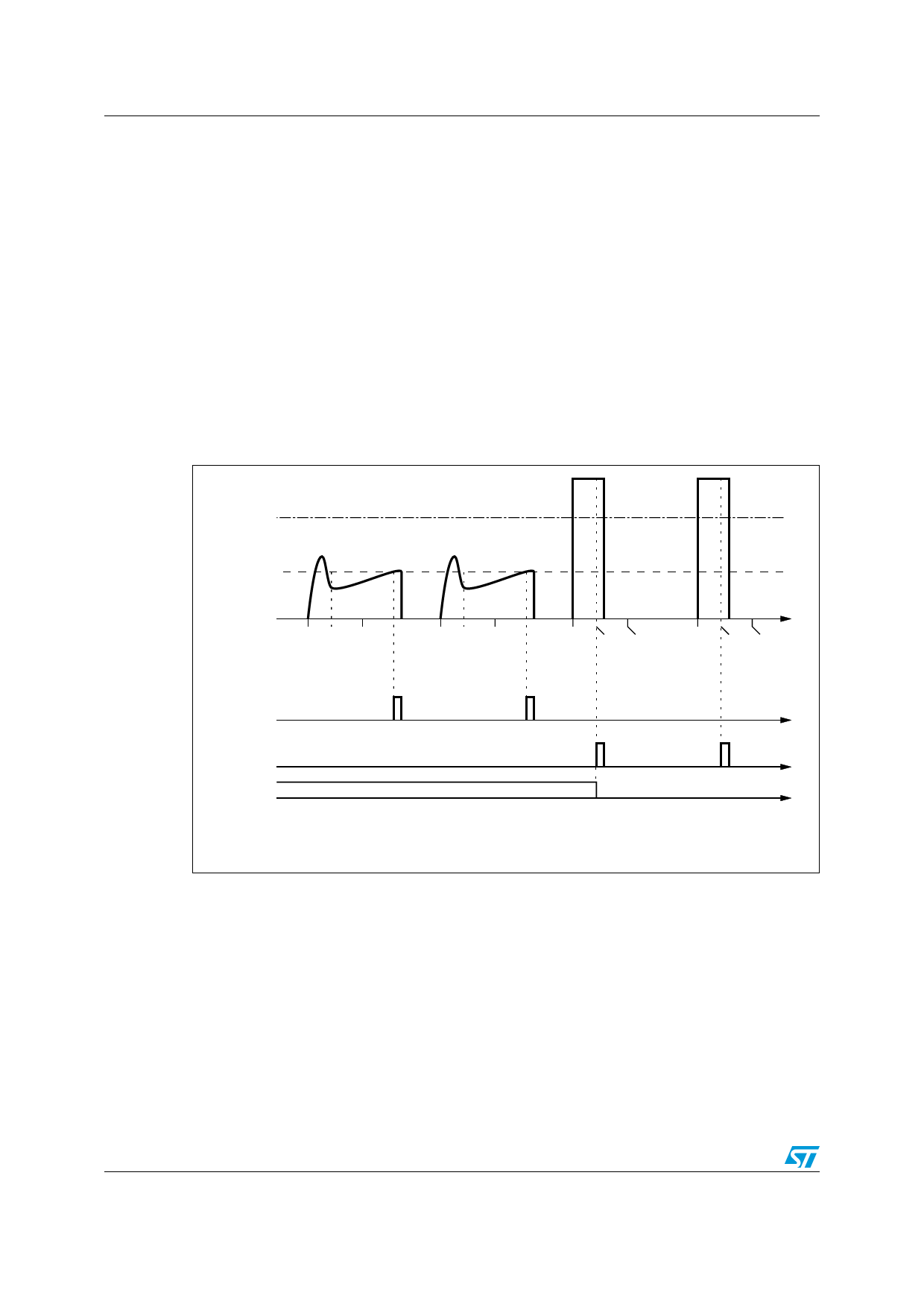
Figure 8. Normal PWM current versus short circuit current and detection of short
to VS
)1�SHORT�THRESHOLD
07-�THRESHOLD
T/. TSHORT T07-
T/. TSHORT T07-
T
T/. TSHORT T07- T/. TSHORT T07-
07-�DETECTION
SIGNAL�INTERNAL
3HORT�DETECTION
SIGNAL�INTERNAL
%RROR�
TON���������������������������TURN�ON�OF�THE�SINK�TRANSISTOR
TON�
�T�
�TSHORT��������ACTIVATION�OF�SHORT�THRESHOLD
TON�
�TDELAY�
�T07-��ACTIVATION�OF�07-�THRESHOLD
T
T
T
'!0'03
Between ton and tshort the over current detection is totally blanked.
Between tshort and tPWM the current threshold is set to 1.5 times the maximum PWM current
(1.5 times the current of current setting LL).
Overcurrent now will set the error flag.
After tPWM the current threshold is the nominal PWM current set by the external resistor.
Exceeding this current will just turn off the sink transistor. This is considered as normal
operation. The error flag is detached from the comparator after tPWM so no error flag is set
during normal pulse width modulation.
16/29
Doc ID 5198 Rev 10
Share Link: 