M-985-01T Ver la hoja de datos (PDF) - Clare Inc => IXYS
Número de pieza
componentes Descripción
Fabricante
M-985-01T Datasheet PDF : 8 Pages
| |||
M-985-01
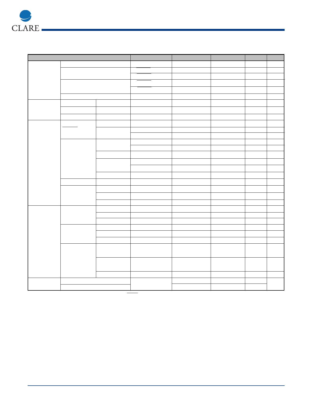
Specifications (Continued)
Parameter
Conditions
Min
Max
Units Notes
Signal Rejection, Frequency Range
950, 1400, 1800 Level: VDD = 5.0V
Hz
Level: VDD = 3.0V
Duration
-
-
-
-
2
XRANGE = open
-
-40 (7.8 mV) dBm
-
XRANGE = VSS
-
-50 (2.5 mV) dBm
-
XRANGE= open
-
-43 (5.5 mV) dBm
-
XRANGE= VSS
-
-
-53 (1.7 mV) dBm
-
50
ms
-
-
Outputs
Inputs
OUT n,
VOL
STROBE pins
VOH
OUT n pins
IOZ
EN, OE,
VIL
XRANGE, MODE, VIH
PD pins
Pull-up and
MODE = VSS
Pull-down currents
/XRANGE = VSS
MODE2 = VDD
PD pin
SIGIN pin
PD = VDD
Pull-down current
Voltage range
Input impedance
ISINK = -1mA
ISOURCE = 1mA
VO=VDD, VSS
-
VDD = 5V
VDD = 2.7V
VDD = 5V
VDD = 2.7V
-
VDD = 5V
VDD = 2.7V
-
PD = VDD
-
f=500 Hz
-
VDD -0.5
-
-
VDD - 2.0
VDD - 0.5
12.5
4
2
12.5
12.5
4
12.5
-6.5
80
0.5
V
-
-
V
-
1
µA
-
0.5
V
-
-
V
-
-
V
-
50
µA
-
20
µA
-
6
µA
-
100
µA
-
25
µA
-
10
µA
-
50
µA
-
VDD
V
-
-
kΩ
-
Input spectrum
-
-
28
kHz
-
Clock
External clock VIL
connected to XIN VIH
pin
Duty cycle
XOUT open
XOUT open
XOUT open
-
VDD-0.2
40
0.2
V
-
-
V
-
60
%
-
XIN, XOUT with Capacitance
-
crystal osc. active Internal resistance
-
-
10
pF
-
20
-
MΩ
-
Tri-state
Operation
X358 pin
Power up (tPU)
VOL
VOH
Duty cycle
tEN (High Z to Low Z)
tDE (Low Z to High Z)
PD hi to lo
CL = 20 pF,
ISINK = -1mA
CL = 20 pF,
ISOURCE = 1mA
CL = 20 pF
CL = 50 pF,
RL = 100 kΩ
-
-
VDD - 0.2
40
-
-
30
ms
-
0.2
V
-
-
V
-
60
%
-
250
ns
-
250
ns
Unless otherwise noted, VDD - VSS = 5V, Ta = 25°C, PD at logical low state, and XRANGE at a logical high state. Power levels are in dBm referenced to 600 ohm. DC voltages are referenced to VSS.
Notes:
1. Per tone.
2. See Table 4 for detection/rejection frequencies.
Call Progress Tone Detection
Call progress tones are audible tones sent from switch-
ing systems to calling parties to show the status of calls.
Calling parties can identify the success of a call placed
by what is heard after dialing. The type of tone used and
its timing vary from system to system, and though
intended for human ears these signals can provide
valuable information for automated calling systems.
The M-985-01 contains five signal detectors sensitive to
the frequencies often used for these progress tones.
Electronic equipment monitoring the OUTn outputs of
the M-985-01 can determine the nature of signals pres-
ent by measuring their duty cycle. See Mechanical
Dimensions for a diagram of a circuit that could be used
to permit a microcomputer to directly monitor tones on
the telephone line. Much of the character of the
progress tones is in their duty cycle or cadence (some-
times referred to as interruption rate). This information,
coupled with level and frequency indication from the M-
985-01, can be used to decide what progress tones
have been encountered.
Rev. 1
www.clare.com
3
Share Link: 