LF2250QC20 Ver la hoja de datos (PDF) - LOGIC Devices
Número de pieza
componentes Descripción
Fabricante
LF2250QC20 Datasheet PDF : 15 Pages
| |||
DEVICES INCORPORATED
LF2250
12 x 10-bit Matrix Multiplier
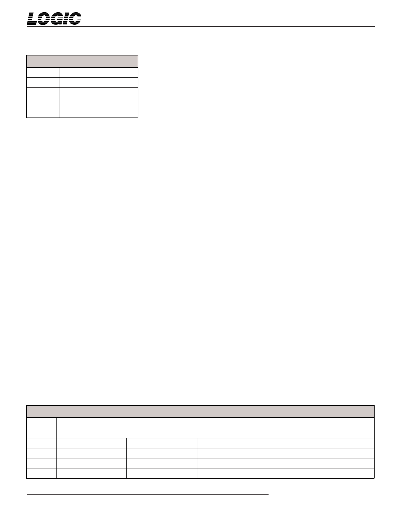
TABLE 1.
MODE1-0
00
01
10
11
MODE SELECTION
OPERATING MODE
3 x 3 Matrix Multiplier
9-Tap FIR Filter
3 x 3 Convolver
4 x 2 Convolver
OPERATING MODES
The LF2250 can realize four different
user-selectable digital filtering architec-
tures as determined by the state of the
mode (MODE1-0) inputs. Upon
selection of the desired function, the
LF2250 automatically chooses the
appropriate internal data paths and
input/output bus structure. Table 1
details the modes of operation.
DATA FORMATTING
The coefficient input ports (KA, KB,
KC) are 10-bit fractional two’s comple-
ment format regardless of the operating
mode. The data input ports (A, B, C)
are 12-bit integer two’s complement
format regardless of the operating
mode.
In the matrix multiplier mode (Mode
00), the data output ports (X, Y, Z) are
12-bit integer two’s complement
format. In the FIR filter and convolver
modes (Modes 01, 10, 11), the X, Y, and
Z ports are configured as the cascade-in
(CASIN15-0) and cascade-out
(CASOUT15-0) ports. These ports
assume 16-bit (12-bit integer, 4-bit
fractional) two’s complement data on
both the inputs and outputs. Table 2
shows the data port formatting for
each of the four operating modes.
BIT WEIGHTING
The internal sum of products of the
LF2250 can grow to 23 bits. However,
in order to keep the output format of
the matrix multiply mode (Mode 00)
identical to the input format, the X, Y,
and Z outputs are truncated to 12-bit
integer words. In the filter modes
(Modes 01, 10, 11), the cascade output
is always half-LSB rounded to 16 bits
(12 integer bits and 4 fractional bits).
The user may half-LSB round the
output to any size less than 16 bits by
simply forcing a “1” into the bit
position of the cascade input immedi-
ately below the desired LSB. For
example, if half-LSB rounding to 12
bits is desired, then a “1” must be
forced into the CASIN3 bit position
(CASOUT4 would then be the LSB).
In all four modes, the user may adjust
the bit weighting, by applying an
identical scaling correction factor to
both the input and output data
streams. If the coefficients are re-
scaled, then the relative weightings of
the cascade-in and cascade-out ports
will differ accordingly. Figure 1
illustrates the input and output bit
weightings for all four modes.
DATA OVERFLOW
Because the LF2250’s matched input
and output data formats accommodate
unity gain (0 dB), input conditions that
could lead to numeric overflow may
exist. To ensure that no overflow
conditions occur, the user must be
aware of the maximum input data and
coefficient word sizes allowable for
each specific algorithm being per-
formed.
SIGNAL DEFINITIONS
Power
VCC and GND
+5 V power supply. All pins must be
connected.
Clock
CLK — Master Clock
The rising edge of CLK strobes all
enabled registers. All timing specifi-
cations are referenced to the rising
edge of CLK.
Inputs
A11-0, B11-0, C11-0 — Data Inputs
A, B, and C are the 12-bit registered
data input ports. Data presented to
these ports is latched into the multi-
plier input registers for the current
operating mode (Table 1). In the filter
modes (Modes 01, 10, 11), the rising
edge of CLK internally right-shifts
new data to the next filter tap.
KA9-0, KB9-0, KC9-0 — Coefficient Inputs
KA, KB, and KC are the 10-bit regis-
tered coefficient input ports. Data
presented to these ports is latched
into the corresponding internal
coefficient register set defined by
CWE1-0 (Table 4) on the next rising
edge of CLK. Table 3 shows which
coefficient registers are available for
each coefficient input port.
TABLE 2. DATA PORT FORMATTING
MODE1-0
00
01
10
11
A11-0
A11-0
A11-0
A11-0
A11-0
B11-0
B11-0
A11-0
B11-0
B11-0
C11-0
C11-0
NC
C11-0
NC
KA9-0
KA9-0
KA9-0
KA9-0
KA9-0
KB9-0
KB9-0
KB9-0
KB9-0
KB9-0
PIN NAMES
KC9-0 XC11-0
KC9-0 X11-0
KC9-0 CASIN15-4
KC9-0 CASIN15-4
KC9-0 CASIN15-4
YC11-8
Y11-8
CASIN3-0
CASIN3-0
CASIN3-0
Y7-4
Y7-4
NC
NC
NC
YC3-0
Y3-0
CASOUT3-0
CASOUT3-0
CASOUT3-0
ZC11-0
Z11-0
CASOUT15-4
CASOUT15-4
CASOUT15-4
Video Imaging Products
2
08/16/2000–LDS.2250-L
Share Link: 