NLV14017BDR2G(2014) Ver la hoja de datos (PDF) - ON Semiconductor
Número de pieza
componentes Descripción
Fabricante
NLV14017BDR2G Datasheet PDF : 8 Pages
| |||
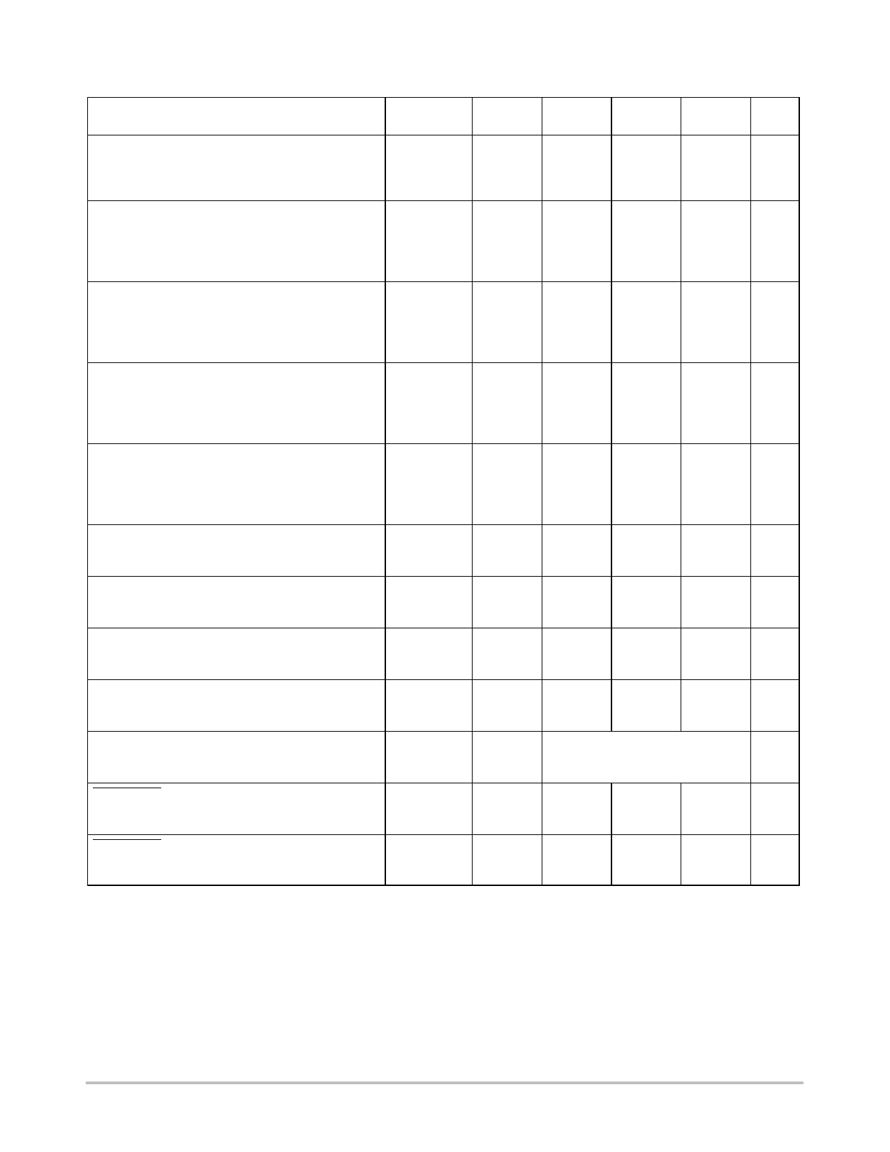
MC14017B
ÎÎSÎÎWIÎÎTCHÎÎINGÎÎCHÎÎARÎÎACÎÎTERÎÎISTÎÎICSÎÎ(NoÎÎte 5)ÎÎ(CLÎÎ= 50ÎÎpF,ÎÎTA=ÎÎ25ÎÎ_C) ÎÎÎÎVDÎÎD ÎÎÎÎÎÎÎÎÎÎTyÎÎp ÎÎÎÎÎÎÎÎÎÎÎÎ
Characteristic
Symbol
Vdc
Min
(Note 6)
Max
Unit
Output Rise and Fall Time
tTLH, tTHL = (1.5 ns/pF) CL + 25 ns
tTLH, tTHL = (0.75 ns/pF) CL + 12.5 ns
tTLH, tTHL = (0.55 ns/pF) CL + 9.5 ns
Propagation Delay Time
Reset to Decode Output
tPLH, tPHL = (1.7 ns/pF) CL + 415 ns
tPLH, tPHL = (0.66 ns/PF) CL + 197 ns
tPLH, tPHL = (0.5 ns/pF) CL + 150 ns
Propagation Delay Time
Clock to Cout
tPLH, tPHL = (1.7 ns/pF) CL + 315 ns
tPLH, tPHL = (0.66 ns/pF) CL + 142 ns
tPLH, tPHL = (0.5 ns/pF) CL + 100 ns
tTLH,
ns
tTHL
5.0
−
100
200
10
−
50
100
15
−
40
80
tPLH,
ns
tPHL
5.0
−
500
1000
10
−
230
460
15
−
175
350
tPLH,
ns
tPHL
5.0
−
400
800
10
−
175
350
15
−
125
250
Propagation Delay Time
Clock to Decode Output
tPLH, tPHL = (1.7 ns/pF) CL + 415 ns
tPLH, tPHL = (0.66 ns/pF) CL + 197 ns
tPLH, tPHL = (0.5 ns/pF) CL + 150 ns
Turn−Off Delay Time
Reset to Cout
tPLH = (1.7 ns/pF) CL + 315 ns
tPLH = (0.66 ns/pF) CL + 142 ns
tPLH = (0.5 ns/pF) CL + 100 ns
Clock Pulse Width
tPLH,
tPHL
tPLH
tw(H)
ns
5.0
−
500
1000
10
−
230
460
15
−
175
350
ns
5.0
−
400
800
10
−
175
350
15
−
125
250
5.0
250
125
10
100
50
15
75
35
−
ns
−
−
Clock Frequency
fcl
5.0
−
5.0
2.0
MHz
10
−
12
5.0
15
−
16
6.7
Reset Pulse Width
tw(H)
5.0
500
250
10
250
125
15
190
95
−
ns
−
−
Reset Removal Time
trem
5.0
750
375
−
ns
10
275
135
−
15
210
105
−
Clock Input Rise and Fall Time
tTLH,
5.0
tTHL
10
15
−
No Limit
Clock Enable Setup Time
tsu
5.0
350
175
−
ns
10
150
75
−
15
115
52
−
Clock Enable Removal Time
trem
5.0
420
260
−
ns
10
200
100
−
15
140
70
−
5. The formulas given are for the typical characteristics only at 25_C.
6. Data labelled “Typ” is not to be used for design purposes but is intended as an indication of the IC’s potential performance.
http://onsemi.com
4
Share Link: 