UEI25-050-D48N-C Ver la hoja de datos (PDF) - Murata Manufacturing
Número de pieza
componentes Descripción
Fabricante
UEI25-050-D48N-C Datasheet PDF : 23 Pages
| |||
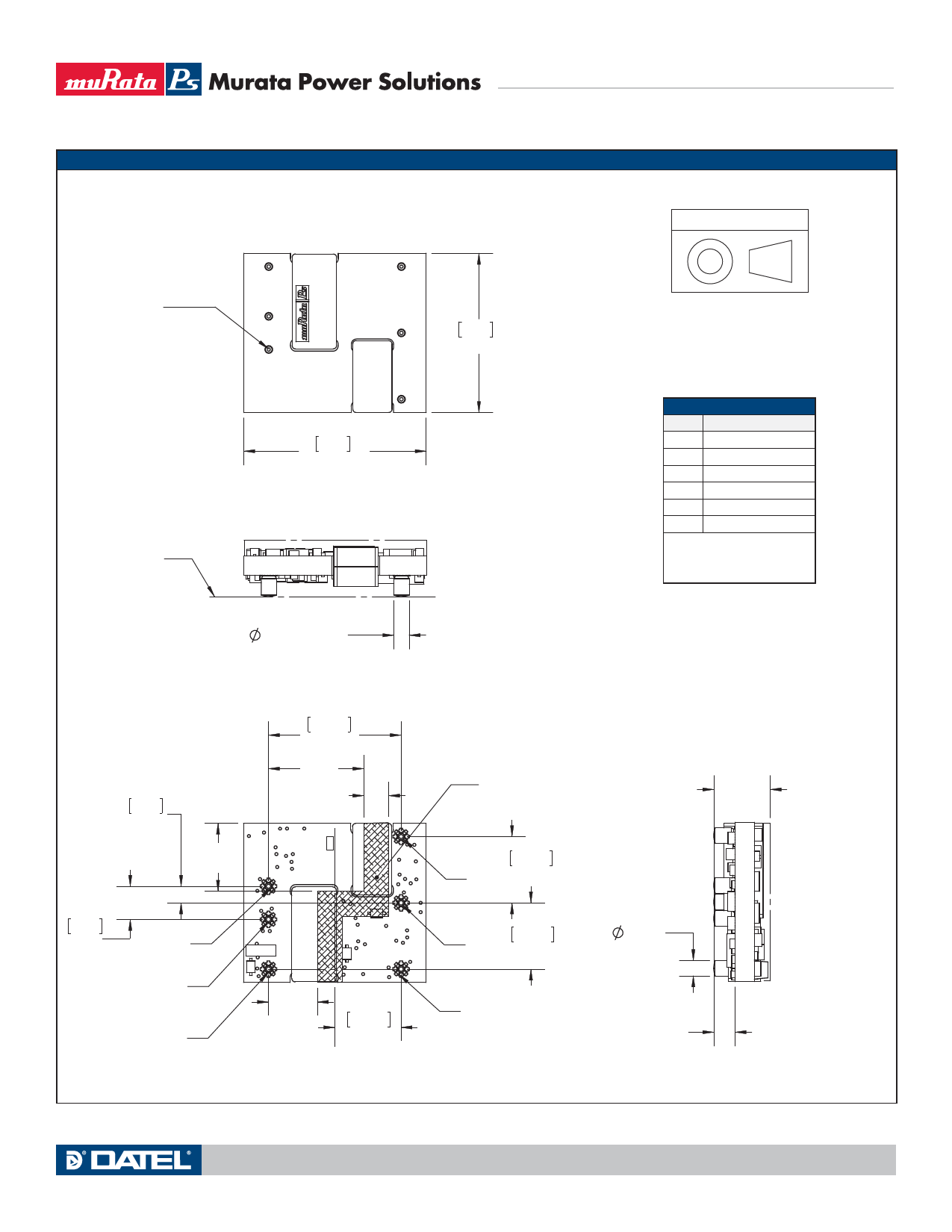
MECHANICAL SPECIFICATIONS, SURFACE MOUNT (MSL RATING 2)
Case 75
TOP VIEW
UEI25 Series
Single Output Isolated 25-Watt DC/DC Converters
Dimensions are in inches (mm shown for ref. only).
Third Angle Projection
PIN #1
MOUNTING
PLANE
27.9
1.10
SIDE VIEW
0.093 [2.4] TYP
2.54
0.100
CL
5.08
0.200
0.41
[10.4]
#1
#2
#6
BOTTOM VIEW
20.32
0.800
0.58
[14.7]
0.15 TYP
[3.8]
0.30
[7.62]
10.16
0.400
CL
24.4
0.96
Tolerances (unless otherwise specified):
.XX ± 0.02 (0.5)
.XXX ± 0.010 (0.25)
Angles ± 1˚
Components are shown for reference only.
INPUT/OUTPUT CONNECTIONS
Pin
Function P85
1
Positive Vin
2
Negative Vin
3
Positive Vout
4
Output Trim
5
Negative Vout
6
On/Off Control*
*The Remote On/Off can be provided
with either positive (P suffix) or nega-
tive (N suffix) polarity
These converters are plug-compatible to
competitive units. In case of pinout numbering
inconsistency, follow the pin FUNCTION, not
the pin number when laying out your PC board.
END VIEW
RECOMMENDED
PRI-SEC BARRIER
10.16
#3
0.400
CL
10.16
#4
0.400
0.093
[2.4]
0.34
[8.64]
MAX
#5
0.13 [3.3]
REF
www.murata-ps.com
MDC_UEI25W.B03 Page 11 of 23
Share Link: 