TA2024C Ver la hoja de datos (PDF) - Unspecified
Número de pieza
componentes Descripción
Fabricante
TA2024C Datasheet PDF : 18 Pages
| |||
Tripath Technology, Inc. - Technical Information
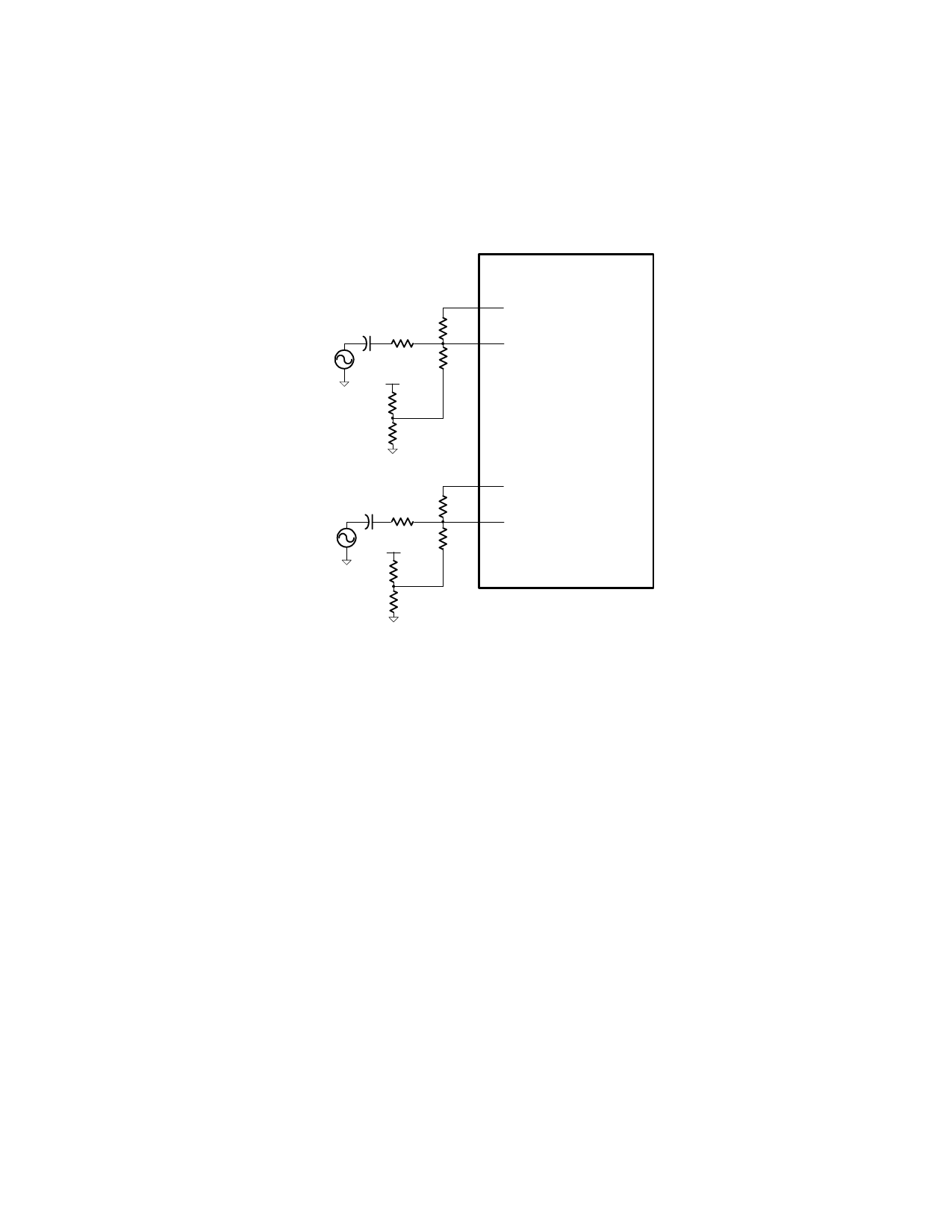
2) In cases where manually trimming potentiometers is not possible, resistors can be used in
place of potentiometers. Since each TA2024C has different offset voltage, the output offset
voltage will need to be measured for both channel 1 and channel 2 and then resistors will
have to be added on the PC board to trim the offset. Below is a lookup table for resistor
values for corresponding offset voltages. Both Rx and Ry values should be 1% tolerance
resistors. Please refer to the EB-TA2024C document for more information on this manual
trim method using resistors.
OAOUT1 29
CI
2.2uF
+
RI
RF
20KΩ
20KΩ
INV1 30
V5A (pin 28)
ROFB
1MΩ
RX1
RY1
TAA2024C
OAOUT2 1
CI
2.2uF
+
RI
RF
20KΩ
20KΩ
INV2 2
V5A (pin 28)
ROFB
1MΩ
RX2
RY2
12
TA2024C –KL/1.0/01.06
Share Link: 