HT6026 Ver la hoja de datos (PDF) - Holtek Semiconductor
Número de pieza
componentes Descripción
Fabricante
HT6026 Datasheet PDF : 7 Pages
| |||
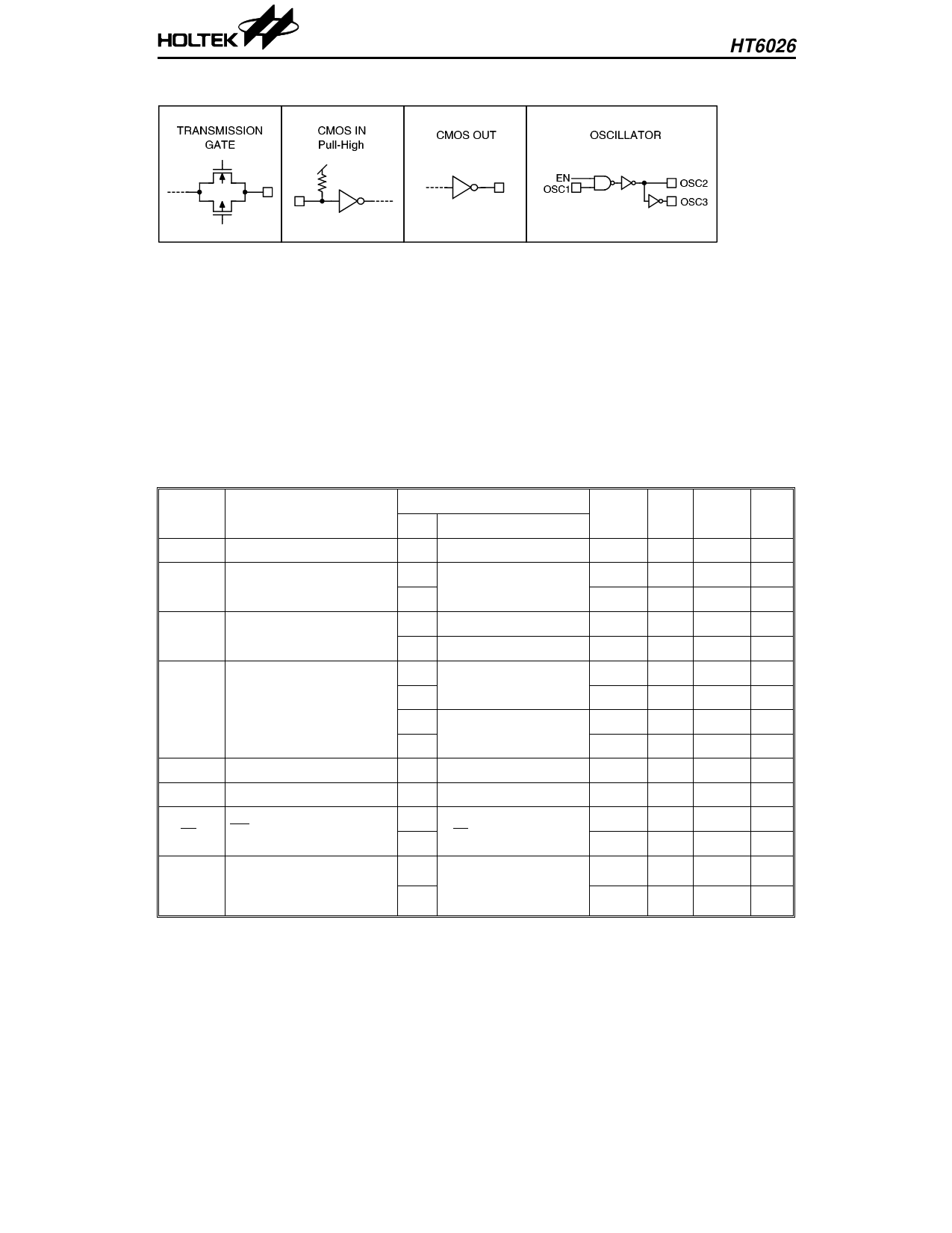
Approximate internal connection circuits
HT6026
Absolute Maximum Ratings*
Supply Voltage ............................... –0.3V to 24V
Input Voltage.................... VSS–0.3 to VDD+0.3V
Storage Temperature................. –50°C to 125°C
Operating Temperature............... –20°C to 75°C
*Note: Stresses above those listed under “Absolute Maximum Ratings” may cause permanent
damage to the device. These are stress ratings only. Functional operation of this device at
these or any other conditions above those indicated in the operational sections of this
specification is not implied and exposure to absolute maximum rating conditions for extened
periods may affect device reliability.
Electrical Characteristics
(Ta=25°C)
Symbol
Parameter
Test Conditions
VDD
Conditions
Min. Typ. Max. Unit
VDD Operating Voltage
—
—
4
—
18
V
ISTB Standby Current
5V
Oscillator stops
15V
—
0.1 0.3 µA
—
0.1 0.5 µA
IDD
Operating Current
5V No load, FOSC=18kHz — 500 900 µA
15V No load, FOSC=22kHz — 2000 3000 µA
5V
–1.0 –1.7 — mA
VOH=0.9VDD (Source)
15V
–8.0 –14.0 — mA
IDOUT Output Drive Current
5V
0.8 1.5 — mA
VOL=0.1VDD (Sink)
15V
5.0 10.0 — mA
VIH
“H” Input Voltage
—
—
0.7VDD — VDD V
VIL
“L” Input Voltage
—
—
0
— 0.3VDD V
5V
RTE
TE Pull-High Resistance
VTE=0V
15V
— 800 — kΩ
— 250 — kΩ
FOSC Oscillator Frequency
5V REXT=10kΩ
CEXT=2000PF
15V RS=20kΩ
—
18
— kHz
—
22
— kHz
3
2nd Oct ’97
Share Link: 